
Understanding and Managing Cable Modem Upstream Transmit Headroom
By Ron Hranac
The following is adapted from a paper titled “Cable Modem Transmit Headroom Resiliency Management,” presented by yours truly during Cable-Tec Expo 2023’s Fall Technical Forum. When the group of 10 coauthors set out to write the paper for Expo, we figured the topic would be straightforward and relatively simple. Boy, were we wrong. Cable modem (CM) upstream transmit headroom is far more complicated than it seems, especially as the upstream radio frequency (RF) spectrum is expanded and more signals are added to that spectrum. The full 39-page paper is a must-read, and is available here: https://www.nctatechnicalpapers.com/Paper/2023/3622_Hranac_5283_paper
Cable operators are extending the operating frequency range of their cable networks, including the upstream. Expanding the upstream operating bandwidth and adding more channels brings with it a variety of challenges, including an impact on CM upstream transmit power capability and headroom. In particular, the modem’s available transmit power spectral density (PSD) is reduced because it must be spread over a wider RF bandwidth. Cable operators face new challenges for managing upstream power in the cable network, because of a complicated system of transmitted RF power, dynamic range window (DRW), long loop automatic level control (ALC), pre-equalization settings, and channel bandwidth. If a CM’s transmitted power is insufficient, then forward error correction (FEC) errors can result, and bit loading may need to be reduced. As well, modems can go into partial service, resulting in those modems being unable to achieve advertised upstream speeds.
Therefore, it is incumbent upon cable operators to manage CM transmit power so that service quality is maintained. As well, understanding the impact of impairments in the spectrum and how they relate to the amount of transmit power “reserve” available to the CM is important. Operators need to focus on the urgency and prioritization of proactive repair in these cases, and also the impact on service, so CM transmit headroom can be effectively managed.
Cable modem upstream transmit power
Data-Over-Cable Service Interface Specifications (DOCSIS®) CM upstream transmitters are designed to accommodate a wide range of net attenuation between each modem and the upstream burst receiver circuitry in a cable modem termination system (CMTS), converged cable access platform (CCAP), or remote PHY device (RPD). Net attenuation in this context includes the combination of all upstream active device gains and coaxial cable and passive device losses in the RF signal path. Further complicating net attenuation is the impact of ambient temperature changes on coaxial cable attenuation from day to night, season to season, and so forth.
What is cable modem transmit headroom?
Generally speaking, a CM’s upstream transmit headroom is the difference, in decibels, between that modem’s maximum transmit power capability and its actual transmit power. But in DOCSIS the CM transmit headroom really has two different interpretations or definitions: 1) CM total composite power (TCP) headroom, and 2) what, in the paper, we call CM minimum channel (Min Ch) headroom. These two headroom values comprise two different figures-of-merit to characterize a CM’s commanded channel power compared to its transmit power capability. An important point: In a plant with tilt and two or more upstream channels, the Min Ch headroom is likely to be the “stop” before the TCP headroom. Additionally, each channel of a CM has its own figure-of-merit in this regard: CM channel headroom. These figures-of-merit are discussed in detail in the Expo paper.
Cable modem total composite power headroom
The CM TCP headroom is the difference between the maximum total composite power capability of the CM, and the total composite power currently commanded (called “reported power” in the DOCSIS specs) to the CM’s transmit channel set (TCS) by the CMTS. Note: To simplify TCP calculations with DOCSIS 3.0 modems, our paper assumed upstream constellations of 32-QAM (time division multiple access, or TDMA) or greater.
Cable modem minimum channel headroom
In DOCSIS 3.1 the CM Min Ch headroom is the difference between the maximum PSD for the CM, which is P1.6hi, and the largest PSD commanded in the TCS:
CM Min Ch headroom (dB) = P1.6hi (dBmV) – max (P1.6r_n, over all N channels)
In DOCSIS 3.0,
Pload_n = Phi_n – Pr_n,
and
Pload_1 = min (Pload_n, over all N channels),
and for our simplifying assumption of TDMA with at least 32-QAM constellations, Phi_1 is 57 dBmV with one channel in the TCS, 54 dBmV with two channels, and 51 dBmV with three or four channels in the TCS, thus:
CM Min Ch headroom (dB) = Phi_1 – Pr_1
Examples: How to calculate CM transmit headroom
The following two examples – one for DOCSIS 3.0 and the other for DOCSIS 3.1 – highlight what’s involved in determining transmit headroom. Additional examples are included in the Expo paper.
DOCSIS 3.0 – Assume four upstream single carrier quadrature amplitude modulation (SC-QAM) channels in the TCS, each with a per-channel power as shown in Figure 1. In this example Pr_1 equals 44 dBmV. Because there are four channels, Phi_n for each channel is 51 dBmV (per the DOCSIS 3.0 PHY spec), so the CM Min Ch headroom is 51 dBmV – 44 dBmV = 7 dB.
The CM’s maximum TCP capability is TCPmax = 51 dBmV + 10log10(4) = 57.02 dBmV.
The TCP of the TCS is
10log10 [10(44⁄10) +10(41⁄10) +10(38⁄10) +10(38⁄10)] = 47.02 dBmV
Here the TCP headroom is 57.02 dBmV – 47.02 dBmV = 10 dB.
DOCSIS 3.1 – Refer to Figure 2, which illustrates a mix of four SC-QAM channels and two orthogonal frequency division multiple access (OFDMA) channels. The powers for the six channels, PWRn, are 37.0 dBmV, 43.0 dBmV, 43.0 dBmV, 43.0 dBmV, 50.0 dBmV, and 57.0 dBmV respectively. The TCP of the TCS is
10log10 [10(37⁄10) + 10(43⁄10) + 10(43⁄10) + 10(43⁄10) + 10(50⁄10) + 10(57⁄10)] = 58.2 dBmV
The CM TCP headroom is Pmax – 58.2 dBmV = 65 dBmV – 58.2 dBmV = 6.8 dB.
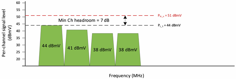
Figure 1. Upstream TCS for DOCSIS 3.0 example.
The CM Min Ch headroom is P1.6hi, 48.2 dBmV (see below), minus the largest P1.6r_n, 43.0 dBmV, which yields 5.2 dB.
Note: P1.6hi = Pmax – 10log10(Neq) = 65 dBmV – 10log10(76.8) = 48.2 dBmV.
Neq in this calculation is the number of 1.6 MHz “chunks” of spectrum that are configured for possible transmission by the modem. In this example,
Neq = (1.6 MHz + 6.4 MHz + 6.4 MHz + 6.4 MHz + 16 MHz + 40 MHz)/1.6 MHz = 76.8.
The largest P1.6r_n of 43 dBmV is the power per 1.6 MHz in the 40 MHz-wide OFDMA signal.
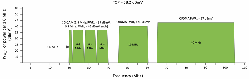
Figure 2. Upstream TCS for DOCSIS 3.1 example.
Factors that can affect transmit headroom
Total composite power – If TCP in the TCS exceeds the maximum supported by the CM, the modem won’t have enough power to maintain such transmission. In this case the CM may be forced to drop one or more of the upstream channels and fall back to partial service, so TCP is within the supported range.
CMTS upstream receive set point – Configuring the CMTS target (receive) set point to a lower or higher level effectively decreases or increases the TCP of the CM’s TCS, which in turn increases or decreases the effective CM headroom.
Transmit channel set occupied bandwidth – Assuming a CM is not already transmitting at its maximum capability, increasing the TCS occupied bandwidth also increases the TCS’s TCP. As the size of a CM’s TCS increases to take advantage of the expanded upstream spectrum, the total combined power of those transmitted channels increases. If the modem was already transmitting at or near its maximum power with a smaller channel load, it may not be able to support the transmit power requirements of added channels.
Dynamic range window (indirect effect) – If the DRW is violated, the fidelity requirements for the TCS may be compromised and eventually the most loaded channel(s) will be dropped from the TCS, forcing the CM to partial service.
Long loop ALC – Anything that causes the net upstream attenuation between modems and the CMTS to change will result in the CMTS telling the affected modems to change their upstream transmit power accordingly.
Upstream pre-equalization – Pre-equalization is normalized so that it will not change the CM transmit power; the CM transmit power remains as commanded. After application of a non-flat pre-equalization, generally the receive power at the burst receiver is reduced because more power was shifted into the parts of the channel with the greatest insertion loss. The overall effect is that the CM needs more transmit power to satisfy the target PSD at the receiver.
Ways to manage cable modem transmit headroom
There are basically three “knobs” to improve transmit headroom:
- Reduce CMTS upstream receive set point
- Reduce the TCS occupied bandwidth
- Fix net attenuation problems
The Expo paper includes guidance for creation of spreadsheets that can be used to model or analyze CM transmit headroom. One of the paper’s coauthors, Alexander Podarevsky, created an online tool for calculating DOCSIS 3.1 CM transmit headroom, available here: https://www.promptlink.com/tools/headroomcalc3.1/
Wrapping up
CM transmit headroom is related to a combination of transmitted RF power, DRW (indirectly), long loop ALC, pre-equalization settings, CMTS receive power set point, and channel bandwidth. All of these factors are even more important as operators migrate to an expanded upstream spectrum, and increase the occupied bandwidth of transmitted signals to support greater data rates. Insufficient CM transmit headroom is an indication that service quality could be impacted by even small changes in plant performance. Thus, it is all the more important that operators properly understand and manage CM transmit power.
A big thanks to the coauthors of our Expo paper and presentation: Roger Fish, Broadcom; Tom Kolze, Broadcom; Satish Mudugere, MaxLinear; Alexander Podarevsky, Promptlink Communications; Jason Rupe, CableLabs; Foad Towfiq, Promptlink Communications; Sheldon Webster, CableLabs; Larry Wolcott, Comcast; and Lei Zhou, Charter.

Ron Hranac
Technical Editor,
Broadband Library
rhranac@aol.com
Ron Hranac, a 51 year veteran of the cable industry, has worked on the operator and vendor side during his career. A Fellow Member of SCTE and co-founder and Assistant Board Member of the organization’s Rocky Mountain Chapter, Ron was inducted into the Society’s Hall of Fame in 2010, is a co-recipient of the Chairman’s Award, an SCTE Member of the Year, and is a member of the Cable TV Pioneers Class of ’97. He received the Society’s Excellence in Standards award at Cable-Tec Expo 2016. He was recipient of the European Society for Broadband Professionals’ 2016 Tom Hall Award for Outstanding Services to Broadband Engineering, and was named winner of the 2017 David Hall Award for Best Presentation. He has published hundreds of articles and papers, and has been a speaker at numerous international, national, regional, and local conferences and seminars.
Images provided by author.