
The Evolution of HFC Transponders: Today’s Possibilities and Tomorrow’s Technology
By Steve Condra –
DOCSIS 4.0 technology, when implemented over soon-to-be-upgraded HFC networks, will cater to the demands of upcoming bandwidth-intensive applications. Yet, certain nuances continue to perplex the cable industry as it plans these upgrades.
Our article begins by discussing how telemetry and transponders are utilized in high-split cable networks to diagnose CPD and ingress issues. Following our example, we broaden the discussion to consider transponders in a wider context, as their applications extend beyond just addressing these issues.
Practical Example: Detecting, Finding, and Solving Ingress and CPD Issues after the Combined High-Split and DAA Roll-Out
Instead of subscribers initiating complaints due to poor network quality, most ingress and CPD issues are first detected by a PNM tool, and occasionally by amplifiers capable of sending ingress alarms to the NMS. The process triggered by the PNM tool is illustrated in Figure 1. When the PNM tool sends an upstream interference alarm (1), it indicates the presence of either ingress or CPD. The PNM tool has access to data generated by the CCAP core, RPDs, and cable modems. This data encompasses, but is not limited to, upstream RxMER per channel and per subcarrier, codeword error ratio (CER), and the upstream spectrum. Consequently, an initial understanding of whether the interference is related to ingress or CPD can be formed early on and confirmed in subsequent stages of the process.
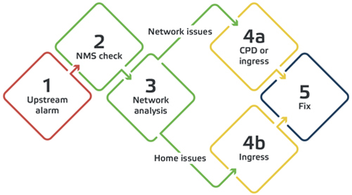
Figure 1. Logical flow of ingress and CPD detection
Next, the NMS is examined (2) to determine if it shows alarms from RF amplifiers below the specific RPD. In such cases, the NMS, rather than the PNM tool, can be utilized to analyze the amplifier upstream inputs more accurately, leveraging a remote connection facilitated by a transponder present in each amplifier. (3) The network is dissected amplifier by amplifier, following the amplifier cascade downwards towards the subscribers. This analysis is based on the upstream attenuation that can be remotely toggled in every amplifier. If this attenuation diminishes the interference level, the interference is confirmed to be already present in the amplifier’s upstream input, and the subsequent amplifier (N+2) is then examined. This investigation continues until the upstream attenuation in the amplifier (N+X) does not affect the level of disturbance. In such an instance, it’s known that the issue enters the network between amplifiers N+X and N+X-1. Even though the process involves multiple steps, it doesn’t have to be time-consuming, as it can be expedited by the NMS.
When interference permeates the network between amplifiers, be it trunk or distribution, a further CPD analysis (4a) is conducted if the interference has a wideband nature. This analysis is executed using the NMS, which can remotely adjust the downstream level/gain of a specific amplifier, as CPD disrupting the upstream is induced by downstream distortion falling over upstream frequencies. Manipulating the downstream level/gain uncovers if the interference is a result of CPD. This information proves valuable for field technicians, as CPD tends to occur in connections close to the amplifier downstream outputs, where the downstream signal level is high, and the upstream signal is relatively low. Consequently, CPD directs field technicians to inspect connections near the amplifier.
Considering that the NMS operates on servers, it can be accessed by authorized personnel either at the headend or in the field. This allows a single individual to autonomously pinpoint and address network issues. If interference is detected below the last amplifier and it’s not related to CPD, the PNM tool can be employed manually to inspect the parameters of the cable modems. If the last amplifier has multiple ports, the number of cable modems requiring examination can be further narrowed down. In such scenarios, the upstream inputs of the chosen amplifier can be attenuated individually. An attenuation can reveal which drop line is the source of ingress. Typically, in these situations, the ingress originates from the subscriber’s premises. Any information that reduces unnecessary customer premises visits—often necessitating separately scheduled appointments—is invaluable. Once the problematic customer premises are identified, the necessary repair can be carried out.
Beyond CPD and Ingress Issues
Transponders are not solely for managing cable network disturbances; they also offer capabilities such as remote alarms, full-band spectrum capture, remote amplifier diagnostics, and remote RF alignment adjustments. Nevertheless, the industry is still deliberating whether transponders, crucial for leveraging advanced telemetry to users’ advantage, should adopt DOCSIS or HMS technologies. Both technologies present distinct advantages, and we aim to concisely enumerate them to assist cable operators in making informed choices. Table 1 outlines these advantages and their associated disadvantages. As DOCSIS 3.0 transponders near the end of their lifecycle, our analysis focuses on DOCSIS 3.1 and its counterpart, the HMSv2 transponders.
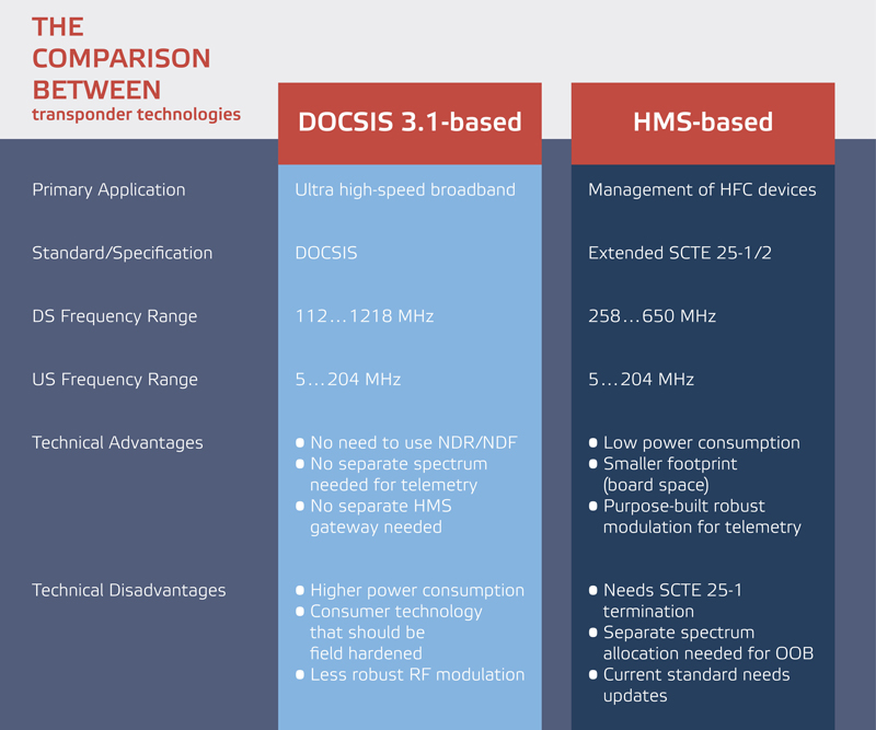
Table 1. Comparison between DOCSIS 3.1-based and HMS-based transponder technologies
DOCSIS was developed for users in pursuit of ultra-fast broadband. DOCSIS modems are consumer devices that operate on household electricity. While power consumption is always a paramount consideration, within a consumer context, it can be offset by enhanced broadband speeds. Furthermore, in-home installations are generally more accommodating than the demanding conditions of outdoor environments. As a result, the environmental conditions that DOCSIS silicon vendors primarily aim to fulfill are less stringent compared to the demands of outdoor settings. Moreover, while certain DOCSIS 3.1 upstream modulation techniques exhibit robustness in noise-heavy conditions, employing them for telemetry negates the distinctive advantage of DOCSIS: its “in-band” communication capability, making it less distinguishable from HMS.
HMS was initially designed to manage HFC network elements. Over time, it has matured into a communication method characterized by low bandwidth and high resilience. The HMS life cycle prioritizes network considerations over subscriber aspects, enabling it to cover multiple DOCSIS versions. Nonetheless, with the rise of distributed access, transitioning to HMSv2 becomes essential. The manner in which SCTE 25-1 is terminated—whether through the RPD software, an out-of-band gateway, or a direct NDF/NDR-to-HMS conversion in the HMS gateway—demands a unified decision from the cable industry. Moreover, collaborative efforts are imperative to address emerging challenges, such as those presented by the ultra-high-split frequency range, as well as issues concerning the security of the supported SNMP version, IPv6 compatibility, and maximum packet/frame size.
While the precise differences in total cost of ownership between DOCSIS and HMS transponders continue to be debated, three key points stand out:
- Supporting both options will increase the costs for next-generation 1.8 GHz amplifiers.
- If the power consumption of 1.8 GHz amplifiers must not surpass that of the older 1 GHz amplifier generations, then HMS becomes the only viable choice.
- Indecision often exacts the greatest cost.
![]()

Steve Condra,
Senior Director Business Development,
Teleste Intercept
Steve Condra has more than 30 years of experience in the telecommunication industry. He spent 16 years with AT&T, Bell Labs, and Lucent Technologies primarily in outside plant design, manufacture, and installation. In addition, he has spent 18 years in the cable TV industry with Scientific Atlanta, Cisco, and currently he works with Teleste Intercept primarily in HFC infrastructure including R&D and product management. Steve earned a Bachelor’s and Master’s degree in Mechanical Engineering from the University of Missouri.
Image: Shutterstock