A Quick Look at S-Parameters
Back in the late 1970s I was an Electronics Technician with TelePrompTer, one of the country’s largest cable operators at the time. Part of my job was equipment testing and repair, some of which involved using fairly simple bench sweep equipment to measure bandwidth, insertion loss, gain, flatness, and so on. In the 1980s I ran Jones Intercable’s corporate engineering lab, evaluating various products for the company. We acquired a vector network analyzer (VNA), which can be thought of as a very sophisticated bench sweep (it actually does a lot more). Operating the VNA meant learning something new to me at the time: scattering parameters, more commonly called S-parameters.
Unless you’re involved with the use of specialized test equipment such as VNAs, S-parameters are likely something you’ve never heard of. At least, perhaps, until recently. In the world of full duplex (FDX) DOCSIS, the S-parameter “S11” is commonly used when discussing an FDX node’s echo cancellation operation. I’ve seen some people refer to S11 as return loss, which it’s not. Return loss can be derived from S11 (more on this later), but the two aren’t quite the same thing. For some background on return loss, see my Broadband Library article on the subject at https://broadbandlibrary.com/return-loss/. So, what are S-parameters? Read on for a high-level overview.
Consider a component or device being evaluated as a “network” with some number of ports N, and a characteristic impedance Z0. For instance, a terminator can be considered a one-port network, as shown in Figure 1.

Figure 1. Cable equipment chassis terminator represented as a one-port network.
An in-line attenuator (or amplifier, tap, etc.) can be considered a two-port network, as shown in Figure 2.
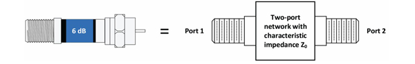
Figure 2. In-line attenuator represented as a two-port network.
Figure 3 shows a line extender amplifier as a two-port network.
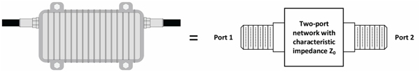
Figure 3. Amplifier represented as a two-port network.
Among the various metrics that can be used to characterize N-port networks are scattering parameters. According to Wikipedia, S-parameters “…describe the electrical behavior of linear electrical networks when undergoing various steady state stimuli by electrical signals.” S-parameters are a simplified representation of a black box network, and are complex numbers — that is, S-parameters have a magnitude and phase component. They are expressed in the format Smn where “m” is the output port number during the measurement and “n” is the input port number during the measurement. For a two-port network, either port can be an input or output port, depending on the measurement; so, in most cases it’s better to refer to port numbers. The “n” subscript also represents the port to which the incident (test) signal is applied. The remainder of this discussion focuses on two-port networks.
Assume that the performance of a two-port network such as an attenuator is being characterized; see Figure 4.
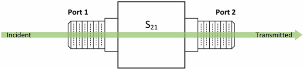
Figure 4. Testing the two-port network from Port 1 to Port 2 gives the S-parameter S21.
A test signal (“Incident”) is applied to Port 1, and that signal (“Transmitted”) is measured at Port 2 after it passes through the device. From an S-parameter perspective this gives us S21, the ratio of transmitted voltage ETransmitted to incident voltage EIncident, called the forward voltage gain or transmission coefficient. As you look at Figure 4, the “21” in S21 indicates the voltage is applied at Port 1 (the “1” in “21”) and is measured at Port 2 (the “2” in “21”). An important point: S-parameters are frequency dependent — that is, the ratio that describes, say, S21, is valid only for a given frequency. As well, S-parameters are referenced at the measurement or interface plane of a network; examples of that plane are Port 1 and Port 2 in Figure 4 (rather than at the test equipment making the measurement).
While the incident signal is being applied to Port 1, we can also measure any reflection from that port. The reflection is a combination of reflections from Port 1’s connector and components inside of the two-port network. Here, the S-parameter is S11, the ratio of reflected voltage EReflected to incident voltage EIncident, and is called the voltage reflection coefficient for Port 1. See Figure 5.
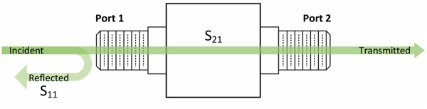
Figure 5. Measuring the reflection from Port 1 gives the S-parameter S11.
Note: When performing a measurement of S-parameters, the port(s) other than the one(s) being measured should be terminated in the network’s characteristic impedance (typically 75 ohms for cable systems). An example is shown in Figure 6 for the case of a reflection measurement at Port 1, with Port 2 terminated.
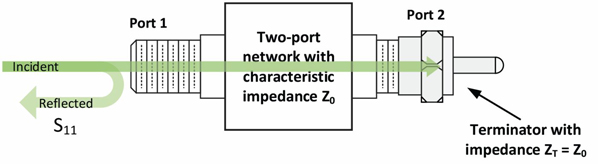
Figure 6. It is common when measuring S11 to terminate Port 2 in an impedance equal to Z0.
Next, apply a test signal to Port 2, and measure at Port 1. This gives us the S-parameter S12, the ratio of ETransmitted to EIncident, and is the reverse voltage gain or transmission coefficient. See Figure 7.
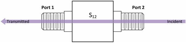
Figure 7. Testing the network from Port 2 to Port 1 gives the S-parameter S12.
A reflection measurement can be made at Port 2, as shown in Figure 8.
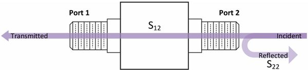
Figure 8. Measuring the reflection from Port 2 gives the S-parameter S22. In many cases Port 1 would be terminated in an impedance equal to Z0 while performing this measurement (terminator not shown).
This gives us the S-parameter S22, or Port 2’s voltage reflection coefficient. Here, too, the reflection is a combination of reflections, in this case from Port 2’s connector and components inside of the two-port network.
In an operational FDX DOCSIS network, the FDX node’s echo cancellation circuitry characterizes the network from the perspective of S11, similar to the example shown in Figure 9.
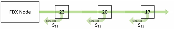
Figure 9. FDX DOCSIS node S11 characterization of the cable network.
Table 1 summarizes the S-parameters just discussed.
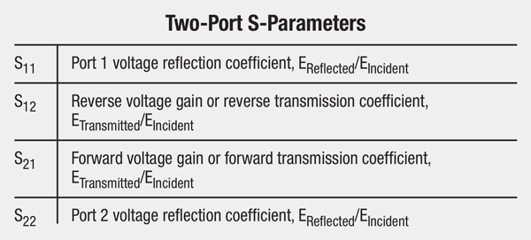
As mentioned previously, for S11 and S22, the voltage reflection coefficient is the ratio of reflected voltage EReflected to the incident voltage EIncident. For S12 and S21, the transmission coefficient is the ratio of transmitted voltage ETransmitted to incident voltage EIncident.
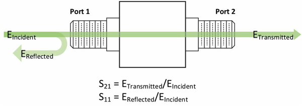
Figure 10. Relationships of EIncident, ETransmitted, and EReflected when measuring from Port 1 to Port 2.
Figure 10 shows the relationships of EIncident, EReflected, and ETransmitted when measuring from Port 1 to Port 2. Here, ETransmitted/EIncident = S21 and EReflected/ EIncident = S11.
Going the other direction, from Port 2 to Port 1, ETransmitted/EIncident = S12 and EReflected/EIncident = S22.
See Figure 11.
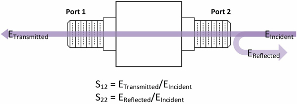
Figure 11. Relationships of EIncident, ETransmitted, and EReflected when measuring from Port 2 to Port 1.
Cable operators are usually more familiar with characteristics such as gain, insertion loss, and return loss, all expressed in decibels. The following formulas are used to derive those metrics from S-parameters (referenced to a two-port network, and assuming Port 1 is the input port and Port 2 is the output port). Voltage standing wave ratio (VSWR) and impedance match also can be derived from S-parameters; see the Wikipedia scattering parameters article referenced below for more information.
Input return loss in decibels Rin = –20log10|S11|
Output return loss in decibels Rout = –20log10|S22|
Gain in decibels GdB = 20log10|S21|
Insertion loss in decibels LdB = –20log10|S21|
If you’d like to learn more about S-parameters, I encourage you to refer to the following.
Wikipedia: Scattering parameters
https://en.wikipedia.org/wiki/Scattering_parameters
Microwaves101.com: S-parameters
https://www.microwaves101.com/encyclopedias/s-parameters
 Ron Hranac
Technical Marketing Engineer,
Cisco Systems
rhranacj@cisco.com
Ron Hranac, a 46-year veteran of the cable industry, is TME for Cisco’s Cable Access Business Unit. A Fellow Member of SCTE and co-founder and Associate Board Member of the organization’s Rocky Mountain Chapter, Ron was inducted into the Society’s Hall of Fame in 2010, is a co-recipient of the Chairman’s Award, an SCTE Member of the Year, and is a member of the Cable TV Pioneers Class of ’97. He received the Society’s Excellence in Standards award at Cable-Tec Expo 2016. He has published hundreds of articles and papers, and has been a speaker at numerous international, national, regional, and local conferences and seminars.
Pingback: What Are S-Parameters and Other Hot Cable Network Topics - Cisco Blogs