Measuring Cable TV Network RF Signal Levels (PART TWO)
By Ron Hranac
In this second installment of a three-part article, the discussion about measurement of downstream RF signal levels continues. Read part one here.
A Closer Look at Factors Contributing to Measurement Gotchas
Signal Source Output Signal Level Accuracy — The purpose of measuring a signal source’s output RF signal level or power is to confirm that it meets a desired value or perhaps some other specified value such as the manufacturer’s published spec. Modern QAM modulators, for instance, are often designed to comply with the technical parameters in the Data-Over-Cable Service Interface Specifications Downstream RF Interface Specification, also known as DRFI. In particular, “Table 6–4 – DRFI Device Output Power,” requires power per channel absolute accuracy to be ±2 dB. That is, a DRFI-compliant modulator’s actual output power must be within ±2 dB of the configured value. Equipment manufacturers may state compliance with DOCSIS® or DRFI specifications1 in published product data sheets. Amplifier and other active devices usually have published specs based upon typical intended use. Those specs can be adjusted by end users for specific deployment scenarios (different channel loading, tilt, cascade depth, etc., compared to the assumptions used in the manufacturer’s published specs).
Signal Source RF Signal Level Stability — Once a device’s output RF signal level has been configured and initially measured, one might assume that the signal level will remain at the set value going forward. However, several things can affect signal level output stability. For example, in the outside coax plant ambient temperature changes will cause the attenuation of the coaxial cable to change2, which in turn causes RF levels in the plant to change. Without automatic gain control (AGC), the output of an amplifier will vary as the RF input signal level from the preceding span of coaxial cable changes over temperature. A headend modulator or other signal source may have an amplitude stability problem that causes the output signal level to vary. Amplitude variation can occur slowly over time, or it can occur quickly over a relatively short period of time. Loose or intermittent connections, cold solder joints, loose center conductor seizure screws, loose modules in nodes and amplifiers (and in headend chassis), are examples of factors that can contribute to output RF signal level instability.
Signal Source Calibration (If Applicable) — As mentioned previously, manufacturers of QAM modulators and similar signal sources calibrate the actual output signal level versus the configured value, using specialized test equipment. Calibration ensures that the signal source meets the manufacturer’s published specifications, and if applicable, a specification such as DRFI. If the calibration was incorrect for some reason, the device’s actual output signal level might not meet published specifications.
Interconnection Net Attenuation — The interconnection between a signal source and the measurement device might exhibit only attenuation – say, coaxial cable, or a combination of coaxial cable and passive devices such as splitters, directional couplers, and in-line attenuators. As well, the interconnection might include a mix of attenuation and gain, the latter from an isolation amplifier or similar.
Net attenuation includes the effects of all attenuation and gain (if applicable) in the signal path. For example, if the interconnection includes an amplifier with 10 dB of gain, and cable and passive attenuation that totals 25 dB, the net attenuation is 15 dB. In any case, interconnection net attenuation must be measured, not assumed.
Measurement Device Accuracy — This is arguably a major source, if not the biggest source, of confusion when making RF signal level measurements. Often the assumption is that if a piece of test equipment reports, say, +15.2 dBmV, that value must be the actual signal level. Test equipment manufacturers specify absolute measurement accuracy for their products. As mentioned in Part One (in the Fall 2017 issue), cable TV handheld and portable field instruments have published accuracy specs ranging from about ±1.5 dB to ±2.5 dB, depending on make/model. Laboratory-grade instruments might have a published accuracy spec of something like ±(0.24 dB + frequency response), where the frequency response is ±0.35 dB.
An instrument’s specified accuracy means that the reported RF signal level can be anywhere within the stated accuracy range. For instance, if the published accuracy spec is ±2.5 dB and the actual net input signal level to that instrument is +15 dBmV, the instrument’s reported value can be anywhere in the +12.5 to +17.5 dBmV range and be considered within spec for that instrument.
Measurement Device Calibration — One often overlooked point is that an instrument’s published accuracy spec depends upon the instrument being periodically calibrated by the factory or a factory-authorized service center. Recommended calibration cycles vary among manufacturers and equipment types, but typically range from every six months to every two years or so. The reason is that instrument calibration can and does change over time. When is the last time your test equipment was factory-calibrated?
Impedance Mismatches — Cable TV networks and their components are designed to have a nominal impedance of 75 ohms. The key here is “nominal,” since the actual impedance is seldom exactly 75 ohms at all frequencies. Every connector, adapter, splitter, amplifier, etc., and even the coaxial cable itself represents an impedance mismatch to some degree. This is normal, and is generally not a problem unless the impedance mismatches are significant. Impedance mismatches can cause standing waves (see Frequency Response) as well as additional mismatch-related loss in the signal path3.
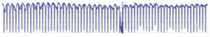
Frequency Response — Ideally the frequency response of the interconnection between a signal source and measurement device should be flat, but this is rarely the case. Coaxial cable has greater attenuation at higher frequencies than at lower frequencies, resulting in non-flat frequency response. The latter can be an issue when measuring signal level over a wide range of frequencies. If impedance mismatches exist in the signal path being measured, standing waves (amplitude ripple) can degrade the frequency response and impact measured signal levels. Standing waves could affect signal levels on channels across the spectrum, as shown in Figure 6. Check signal levels on several adjacent channels or observe on a spectrum analyzer to see if standing waves are present in the spectrum.

- DOCSIS is a trademark owned by Cable Television Laboratories, Inc.
- Coaxial cable attenuation in dB varies about 1 percent per 10 ˚F of temperature change.
- For example, the published attenuation values for coaxial cable are known as matched loss values – that is, the values assume the cable is connected to a load impedance equal to the cable’s characteristic impedance. If the cable is connected to a load impedance that is not equal to the cable’s characteristic impedance, the attenuation of the cable will be higher than its matched loss by an amount that depends on the severity of the impedance mismatch. See https://en.wikipedia.org/wiki/Mismatch_loss.
Part Three will appear in the Spring 2018 issue of Broadband Library, and will conclude the discussion about factors that affect signal level measurements and provide tips to achieve more accurate results.
 Ron Hranac
Technical Leader,
Cisco Systems
Ron Hranac, a 45-year veteran of the cable industry, is Technical Leader for Cisco’s Cable Access Business Unit. A Fellow Member of SCTE, Ron was inducted into the Society’s Hall of Fame in 2010, is a co-recipient of the Chairman’s Award, an SCTE Member of the Year, and is a member of the Cable TV Pioneers Class of ’97. He received the Society’s Excellence in Standards award at Cable-Tec Expo 2016. He has published hundreds of articles and papers, and has been a speaker at numerous international, national, regional, and local conferences and seminars.
Credit: Cartoonstock.com
Credit: Shutterstock.com