Downstream RF Signal Levels (PART ONE)
By Ron Hranac
Optimum cable network downstream performance requires that radio frequency (RF) signal levels be measured and set correctly. RF signal levels affect nearly every part of a cable network’s operation: headend/hub site, optical fiber links, coax distribution, subscriber drops, and customer premises equipment (CPE).
Measurement of a cable network’s RF signal levels is often taken for granted. The procedure is seemingly straightforward: Connect a signal level meter (SLM), spectrum analyzer, or similar instrument to the device or signal source being measured, and read the reported signal level (see Figure 1). But is the reported value the actual value? Not necessarily. There are several factors that affect the results of a signal level measurement. This article discusses some of those factors, and how to achieve more accurate and repeatable results.
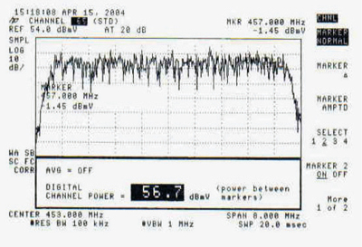
Figure 1. Is the reported digital channel power of 56.7 dBmV the actual digital channel power?
What is Signal Level?
Signal level is the amplitude of a signal, specifically the RF power of that signal. Signal level in cable networks is expressed in decibel millivolt (dBmV) or decibel microvolt (dBµV), where dBmV and dBµV are units of power expressed in terms of voltage. In the case of an analog TV signal’s visual carrier, signal level is the carrier’s peak envelope power (PEP). The signal level of a quadrature amplitude modulation (QAM) or orthogonal frequency division multiplex (OFDM) signal is its average power (measured in the occupied bandwidth of the entire signal, or in some specified bandwidth), also called digital channel power or digital signal power.
General RF Signal Level Measurements
Measurement of RF signal level involves taking into account three major components, shown in Figure 2.

Figure 2. Basic signal level measurement setup
The first component, the signal source, provides an RF signal (or signals) whose level is an assumed or perhaps unknown value. The second component, the interconnection, could be something as simple as a short length of coaxial cable, or may be more complex (e.g., headend combining/splitting network) and include a combination of gain and loss. The third component is the measurement device, the test instrument used to measure the signal source’s RF signal level.

All three components shown in the figure have an impact in one or more ways on the measured signal level. Among the major factors that affect the measurement results are the signal source’s accuracy and stability, and depending on the nature and type of source, its calibration; the net attenuation in the interconnection; and the measurement device’s accuracy and calibration. Other factors such as impedance mismatches, frequency response flatness, and temperature also affect signal level measurement.
The signal level present at the measurement device is the net signal level, which is the difference between the signal source output signal level and the net attenuation through the interconnection.
Two Important Terms
Characterizing signal level measurements requires an understanding of related terminology. In particular, the words accuracy and precision can cause a fair amount of confusion. While related, they do not mean the same thing. The following definitions are from ISO 5725-1 [1].
Accuracy — the closeness of agreement between a test result and the accepted reference value
Precision — the closeness of agreement between independent test results obtained under stipulated conditions
When measuring RF signal levels, it is possible for measurement results to be precise but not accurate; to be both precise and accurate; and to be neither precise nor accurate. Clearly, the desired goal is measurement results that are both precise and accurate.
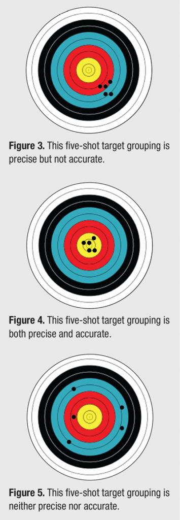
To help understand the concepts of accuracy and precision, consider an analogy in which an archer shoots arrows at a target. The points where the archer’s arrows hit the target can be described in terms of accuracy and precision, as illustrated in Figure 3, Figure 4, and Figure 5. The small black dots on each target represent where the arrows hit the target.
Applying the archery analogies to RF signal level measurements, assume a QAM modulator whose per-channel output power is +50 dBmV. For the example in Figure 3, five successive signal level measurements using the same test instrument might report +45.9 dBmV, +46.2 dBmV, +46.0 dBmV, +45.8 dBmV, and +46.1 dBmV. These five measurement results are precise but not accurate.
For the example in Figure 4, five successive signal level measurements using the same test instrument might report +49.8 dBmV, +50.3 dBmV, +49.6 dBmV, +49.9 dBmV, and +50.2 dBmV. These five measurement results are both precise and accurate.
For the example in Figure 5, five successive signal level measurements using the same test instrument might report +46.7 dBmV, +53.1 dBmV, +53.9 dBmV, +47.1 dBmV, and +54.0 dBmV. These five measurements are neither precise nor accurate.
Lab-Grade versus Field-Grade Measurement Devices
Manufacturers of headend and hub site signal sources such as cable modem termination systems (CMTSs) and QAM modulators use specialized lab-grade test equipment to ensure that their products comply with published specifications. During manufacture, the signal sources are calibrated such that their configured output RF signal level and their measured output RF signal level meet or exceed a specified power- per-channel absolute accuracy. In order to ensure the latter, the absolute measurement accuracy of the test equipment used by the manufacturer must be better than the signal source’s specified power-per-channel absolute accuracy.
For example, if the signal source’s specified power per channel absolute accuracy is ±2 decibels (dB) relative to the configured value, the test equipment used to calibrate the signal source must have an absolutely accuracy better than ±2 dB. Lab-grade instruments have accuracy specs that are typically ±1 dB or less.
 Field-grade measurement devices used by cable technical personnel have published absolute accuracy specs that range from about ±1.5 dB to ±2.5 dB, depending on make/model. A measurement device with ±1.5 dB absolute accuracy might be suitable for confirming whether a CMTS or QAM modulator with ±2 dB accuracy meets its own published spec, but instruments with ±2 dB or ±2.5 dB absolute accuracy would not be suitable in this example.
Bibliography: [1] ISO 5725-1:1994 “Accuracy (trueness and precision) of measurement methods and results — Part 1: General principles and definitions”
Part 2 will appear in the Winter 2017 issue of Broadband Library, and will continue the discussion about factors that affect signal level measurements and provide tips to achieve more accurate results.
 Ron Hranac
Technical Leader,
Cisco Systems
Ron Hranac, a 44-year veteran of the cable industry, is Technical Leader for Cisco’s Cable Access Business Unit. A Fellow Member of SCTE, Ron was inducted into the Society’s Hall of Fame in 2010, is a co-recipient of the Chairman’s Award, an SCTE Member of the Year, and is a member of the Cable TV Pioneers Class of ’97. He received the Society’s Excellence in Standards award at Cable-Tec Expo 2016. He has published hundreds of articles and papers, and has been a speaker at numerous international, national, regional, and local conferences and seminars.
Credit: Cartoonstock.com
Credit: Shutterstock.com