Signal Leakage
By Ron Hranac
Signal leakage – sig·nal (sig’n’l) leak·age (lek’ij) The unwanted emission of radio frequency (RF) signals from inside of a cable network into the over-the-air environment, usually caused by degraded shielding effectiveness of the network’s cables and/or other components. Also called egress.
A closed network
Coaxial cables and other pieces and parts used in the RF distribution and subscriber drop portions of a cable TV network provide a shielded transmission medium that is independent of the over-the-air environment. Over-the-air frequencies are allocated to various services, typically by government agencies, while cable operators largely enjoy the ability to use frequencies within their networks as they see fit (operators in some countries are prohibited from using certain frequencies in their networks).
A cable TV network is ideally a closed transmission medium, allowing the use of frequencies or channels inside of the coaxial cables and components that may be used for something else altogether in the over-the-air environment. This is called frequency reuse, which allows cable operators to provide a wide variety of services via their broadband networks.
The rules
In the U.S., Part 76 of the FCC Rules [1] spells out the maximum allowable signal leakage field strength limits in microvolts per meter (μV/m) at specified measurement distances—shown in Table 1—and requirements for other aspects of leakage-related issues.
There is an important requirement in §76.613 that some people are unaware of or may have forgotten. That’s the harmful interference clause, which basically says if leakage causes harmful interference as defined in the rules—regardless of the leak’s field strength—it must be fixed ASAP. If you haven’t read that important clause, I encourage you to do so sooner rather than later to avoid potentially serious consequences.
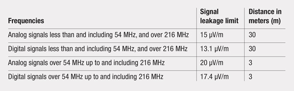
Table 1. Signal leakage limits from §76.605(c) of the FCC Rules.
What causes signal leakage?
If the shielding integrity of the cable network is compromised for any reason, then RF signals inside of the coaxial cables and components can leak out and potentially interfere with licensed over-the-air services. Going the other direction, over-the-air signals can leak into the cable network (this is called ingress), and potentially interfere with cable signals.
Here are a few examples of signal leakage sources:
- Poorly shielded customer premises equipment (CPE) connected directly to the subscriber drop
- Inadequately shielded cable and equipment (can be a problem near high-power transmitters)
- Loose, damaged, or improperly installed connectors, adapters, and splices
- Damaged cable shielding: abrasion, burns, bullet and pellet holes, corrosion, cracks, cuts, rodent chews, staple through drop cable
- Damaged RF gaskets on passive and active device housings and faceplates
- Loose passive device faceplates
- Loose or warped amplifier housing lids
- Retail-grade cables, connectors, passives (typically purchased and installed by subscribers)
- Theft of service
Point of confusion
One of the most commonly misused terms in the world of signal leakage is CLI, which is an abbreviation for cumulative leakage index. CLI is NOT the same thing as signal leakage! CLI is a mathematical snapshot of a cable system’s overall signal leakage performance at a given point in time. Here’s the formula from Part 76 for calculating CLI:
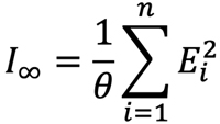
One cannot detect, test, measure, or even repair CLI; one must measure signal leakage in order to calculate CLI. Want to improve a system’s CLI? Find and fix signal leakage.
Measuring leakage
The metric of interest for leakage is its field strength in microvolts per meter (not just microvolts), which is typically measured with a dedicated signal leakage detector. Modern leakage detectors are digital-compatible and operate on multiple frequencies [2],[3]. Leakage test signals are generated in the headend or hub (or in a distributed access architecture’s remote PHY device-equipped node), and transmitted in the downstream spectrum. Many detectors, depending on make/model, can be mounted in vehicle-installed cradles that are connected to roof-top antennas, allowing leakage to be monitored while system personnel are driving to and from their jobs. Some leakage detection equipment operates with GPS so that the location of leakage (and its field strength) can be automatically recorded for analysis later and even plotted on system maps. When tracking down and measuring specific leaks, the detectors can be removed from their cradles and used handheld with integrated antennas. Some handheld detectors can be connected to portable external antennas or probes for narrowing down the leakage source.
I often see posts on social media showing techs holding a detector just inches from a cracked cable or similar, commenting about how high the leakage field strength is. It is important to note that to obtain accurate field strength values, leakage should be measured in what is called the source’s far-field region. The accuracy of field strength measurements made inside of what is called the near-field region is questionable at best. Changing the detector’s distance offset doesn’t really help, because in the near-field region the field strength intensity-versus-distance no longer follows the inverse square law. See Figures 1 and 2. A discussion about near- and far-field regions, and various leakage-related equations can be found in [4].
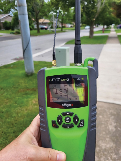
Figure 1. Leakage field strength at 756 MHz and 126 MHz is 180 μV/m, measured about 3 meters from the source (the camera distorts the distance perspective). This measurement is in the far-field region for both frequencies. Image courtesy of Arni Lundale.
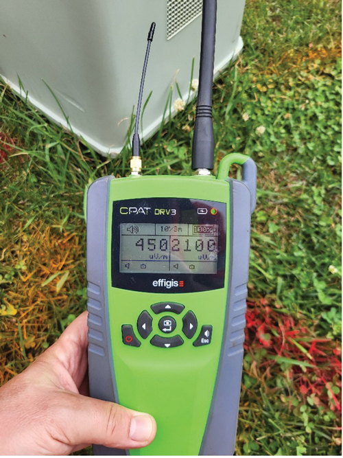
Figure 2. When measured a little less than 1 meter from the source, the indicated field strengths are 450 μV/m at 756 MHz and 2100 μV/m at 126 MHz. The detector is still in the far-field region for the higher frequency, but is in the near-field region for the lower frequency. Image courtesy of Arni Lundale.
Leakage monitoring in a high-split plant
In a high-split architecture the 108 MHz to 137 MHz VHF aeronautical band overlaps part of the cable network’s upstream spectrum. That means downstream leakage test signals are no longer practical for signal leakage monitoring in or near the VHF aeronautical band (downstream leakage signals can still be used at higher frequencies, of course). What to do? One solution is to use OFDMA upstream data profile (OUDP) testing burst signals transmitted by DOCSIS 3.1 cable modems in subscribers’ homes. That requires OUDP-compatible leakage detectors and a somewhat different approach to monitoring and measurement [5].
Wrapping up
Signal leakage has been important for as long as I’ve been in the cable industry. I remember my colleagues doing leakage testing back in the early 1970s, and I started doing it a few years later. Over the years the FCC Rules, the test equipment, and even the types of signals we monitor have evolved. But the fundamentals haven’t changed. The value of keeping the plant tight helps to avoid harmful interference to over-the-air users. An effective leakage monitoring and repair program also helps to reduce ingress problems, and ensures better network performance.
Additional resources
[1] FCC Rules, Part 76, Subpart K, Technical Standards (https://www.ecfr.gov/current/title-47/chapter-I/subchapter-C/part-76)
[2] Hranac, R., G. Tresness. “Another Look at Signal Leakage: The Need to Monitor at Low and High Frequencies,” Technical Workshop Proceedings, SCTE Cable-Tec Expo, Oct. 17-19, 2012, Orlando, FL
[3] Hranac, R., N. Segura. “UHF Signal Leakage and Ingress: Understanding the Liability and Risk,” Technical Workshop Proceedings, SCTE Cable-Tec Expo, Oct. 21-24, 2013, Atlanta, GA
[4] SCTE 270 2021r1 Mathematics of Cable (https://www.scte.org/standards/library/catalog/scte-270-mathematics-of-cable/)
[5] Segura, N., “OUDP Bursts for High-Split RF Leakage Detection,” Summer 2022 issue of Broadband Library (https://broadbandlibrary.com/oudp-bursts-for-high-split-rf-leakage-detection/)
 Ron Hranac
Technical Editor,
Broadband Library
rhranac@aol.com
Ron Hranac, a 51 year veteran of the cable industry, has worked on the operator and vendor side during his career. A Fellow Member of SCTE and co-founder and Assistant Board Member of the organization’s Rocky Mountain Chapter, Ron was inducted into the Society’s Hall of Fame in 2010, is a co-recipient of the Chairman’s Award, an SCTE Member of the Year, and is a member of the Cable TV Pioneers Class of ’97. He received the Society’s Excellence in Standards award at Cable-Tec Expo 2016. He was recipient of the European Society for Broadband Professionals’ 2016 Tom Hall Award for Outstanding Services to Broadband Engineering, and was named winner of the 2017 David Hall Award for Best Presentation. He has published hundreds of articles and papers, and has been a speaker at numerous international, national, regional, and local conferences and seminars.