Long Loop ALC
By Ron Hranac
A surprising amount of behind-the-scenes interaction occurs between Data-Over-Cable Interface Service Specifications (DOCSIS®) cable modems and the cable modem termination system (CMTS). One important process is called station maintenance, during which the received upstream signals are evaluated by the CMTS. The CMTS looks at the received signal level, the signal’s center frequency, its timing, and other parameters. If any of those are out of whack, the CMTS will command the affected modem to adjust its transmitted signal as needed (Brady Volpe has a nice overview of station maintenance on his web site at https://volpefirm.com/docsis_station-maintenance/).
In particular, the received upstream signal level is supposed to match the CMTS’s commanded nominal receive power, which has a default value of 0 dBmV in most CMTSs (that value is user configurable). If the received upstream signal level doesn’t match the commanded nominal receive power, the CMTS “tells” the modem via a ranging response (RNG-RSP) message to adjust its upstream transmit power as needed so the received signal level at the CMTS is correct. This upstream signal level management is called long loop automatic level control (ALC).
Why would a cable modem’s upstream transmit level need to be changed after it was initially set when the modem first came online? One important reason is related to coaxial cable attenuation variations as the temperature changes. Cable attenuation increases when it’s warm, and decreases when it’s cold.1 For example, as the temperature drops during the night, the cable attenuation in the outside plant decreases, which means upstream signal levels in the drop and coax distribution network increase, as does the upstream input to the CMTS. The CMTS commands the modems to decrease their upstream transmit power until the received signal level in the headend or hub is the correct value once again. The next day, as the cable attenuation increases because of warmer temperatures, the input to the CMTS decreases. To compensate for that, the CMTS commands the modems to increase their upstream transmit power. This process also happens as the seasons change.
Indeed, anything that causes the net upstream attenuation between modems and the CMTS to change will result in the CMTS telling the affected modems to change their upstream transmit power accordingly.
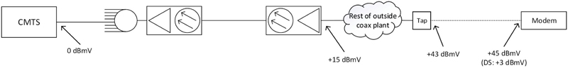
Let’s look at a few examples, starting with a scenario in which a given subscriber has only high-speed Internet service. Figure 1 shows what the typical upstream signal levels might be. The downstream input to the modem is +3 dBmV, the modem’s upstream transmit power is +45 dBmV, and that upstream signal’s RF level at the input to the tap (after drop cable loss) is +43 dBmV. By the time the signal reaches the node, it’s +15 dBmV. Assume that this setup gives us the desired 0 dBmV at the CMTS upstream port.
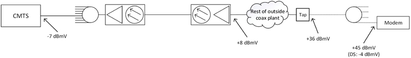
Now assume the same subscriber decides to have three TVs connected along with the existing cable modem. An installer is dispatched to the subscriber premises to install the additional outlets, cabling, and four-way splitter. What happens to the upstream signals with the additional 7 dB of loss from the splitter? In Figure 2, we see that for a brief amount of time the modem’s upstream signal is reduced by 7 dB, giving us +36 dBmV at the tap, +8 dBmV at the node, and -7 dBmV at the CMTS upstream port. The modem’s transmit level is still at its original +45 dBmV, but the downstream input to that modem has dropped by 7 dB from +3 dBmV to -4 dBmV.
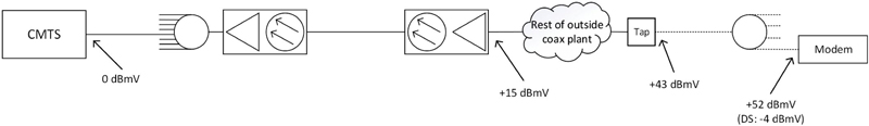
The station maintenance process measures the lower input to the CMTS, and commands the modem via a RNG-RSP message to increase its transmit power by 7 dB (see Figure 3). Now the modem’s upstream transmit level is +52 dBmV. Note that the input to the tap is back to the original +43 dBmV, the node input is +15 dBmV, and the CMTS input is 0 dBmV. The downstream level at the modem input is still 7 dB lower than its original value, though.
Quick side note: I’ve heard some techs say that adding attenuation causes upstream levels to increase, which isn’t the full story. The additional attenuation — whether from a splitter, pad, or something else — decreases all RF signal levels by the amount of that attenuation. What changes is the modem’s upstream transmit power, in order to overcome the additional attenuation.
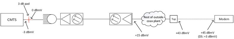
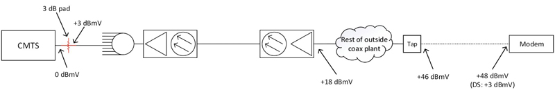
Let’s look at another scenario, starting with the original drop configuration in Figure 1. In this example a 3 dB pad (attenuator) is installed in the headend or hub at the upstream input to the CMTS, as shown in Figure 4. What happens to the signal levels? First, the downstream input to the modem is not affected, and remains at the original +3 dBmV. Until the station maintenance process detects what has happened, the upstream input to the CMTS is reduced by 3 dB, from 0 dBmV to -3 dBmV, and the upstream levels in the plant (modem output, input to tap, input to node) are unchanged.
As soon as the station maintenance process detects the 3 dB signal level drop at the CMTS upstream port, it commands the modem to increase its upstream transmit level by 3 dB, from the original +45 dBmV to +48 dBmV (the same thing happens to all other modems connected to the same CMTS upstream port). Here, the upstream levels at the input to the tap, node (and upstream optical receiver output), and input to the 3 dB pad have all increased by 3 dB (Figure 5).
One advantage to installing a pad at or near the input of the CMTS is that the upstream carrier-to-junk ratio can be improved by the amount of the attenuation because the upstream signal levels have gone up by 3 dB, but noise and ingress are the same as before. Two potential gotchas are (1) if the upstream optical link is operating close to its compression threshold, higher upstream input to the node could cause laser clipping, and (2) modems already operating at their maximum upstream transmit level won’t be able to increase their transmitted RF power beyond that maximum. As a result, those modems’ upstream signals at the CMTS input will be lower than other modems’ levels, likely received below the commanded nominal receive power, and have worse carrier-to-junk ratio and lower receive modulation error ratio (RxMER) than other modems.
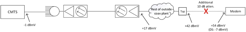
A max’d out modem is illustrated in Figure 6, in which 10 dB of additional attenuation in the drop — say, from cable damage — affects downstream and upstream levels. Here, let’s assume the modem’s maximum transmit power is +54 dBmV. Upstream levels for that modem at the input to the tap, node, and CMTS will all be 1 dB lower than the original values shown in Figure 1, because the modem was able to increase its transmit level by only 9 dB (from +45 dBmV to +54 dBmV) instead of the full 10 dB needed to overcome the additional 10 dB of drop attenuation. The downstream input to the modem is also 10 dB low.
Long loop ALC is an important part of DOCSIS cable modem operation, and helps to maintain correct upstream RF input to the CMTS. Modems support a fairly wide range of upstream transmit levels, which in turn provides the dynamic range to accommodate a wide variety of plant and drop conditions.
[1] Coaxial cable attenuation in decibels changes about 1% for every 10 °F ambient temperature change. Both downstream and upstream levels are affected by temperature-related cable attenuation changes.
 Ron Hranac
Technical Marketing Engineer,
Cisco Systems
rhranacj@cisco.com
Ron Hranac, a 46-year veteran of the cable industry, is TME for Cisco’s Cable Access Business Unit. A Fellow Member of SCTE and co-founder and Associate Board Member of the organization’s Rocky Mountain Chapter, Ron was inducted into the Society’s Hall of Fame in 2010, is a co-recipient of the Chairman’s Award, an SCTE Member of the Year, and is a member of the Cable TV Pioneers Class of ’97. He received the Society’s Excellence in Standards award at Cable-Tec Expo 2016. He has published hundreds of articles and papers, and has been a speaker at numerous international, national, regional, and local conferences and seminars.