OUDP Bursts for High-Split RF Leakage Detection
By Nick Segura
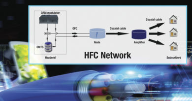
HFC high-split architectures are rolling out and the Federal Communications Commission expects cable operators to adhere to compliance requirements in Part 76 of the FCC rules.
Traditional RF leakage test systems leverage downstream signal sources that typically emanate from the headend/hub today. In a high-split architecture the 108 MHz to 137 MHz aeronautical band is now in the upstream path! How can we measure upstream leakage? DOCSIS 3.1 cable modems can be commanded by the CMTS to generate target OFDMA upstream data profile (OUDP) signals and an updated RF leakage meter can be used to accurately measure this narrow portion of the OFDMA upstream carrier. How will this work?
Risks and rewards
There are inherent risks associated with moving carriers around within the designated bandwidth we are allocated, and this effort to invent a new way of performing signal leakage measurements is one of several radical changes. Beware, it is easy to get lost in designing a solution for the problem at hand, rather than thinking like a systems architect who envisions what could be and uses models to compute particular outcomes for realizing future benefits of the high-split changes. These modern tool solutions must be expedient and our technicians must be ready to use them because “you cannot manage what you don’t measure,” and maintaining visibility of egress, especially so close to the FM band, allows for our industry’s coexistence with aviation communication, mobile first-responders and other obligatory FM/VHF/UHF band signals.
Regulatory awareness
It bodes well for a cable operator to show a noticeable level of effort for the FCC to see when managing RF emissions from their coaxial networks, and they must ultimately understand risks defined in §76.613, the harmful interference clause of Part 76. Although regulatory compliance may be a cable operator’s first concern (avoid fines), the fear of receiving an FCC order to mute precious bandwidth is just as terrible. By maintaining the existing 138 MHz monitoring location, and potentially adding others in newly activated portions of spectrum above 860 MHz, maintaining the visibility to troubleshoot harmful interference issues with over-the-air service providers will keep us all in business.
Will it work?
It is refreshing to have distinguished industry professionals in our business to support rapid firmware updates for CMTSs and remote PHY nodes. The brightest minds originally explored four methods to support high-split leakage detection and measurement and settled on the OUDP test burst methodology partially because it is already part of the DOCSIS 3.1 and 4.0 CM standard.
Under control of the CMTS, a CM sends an OUDP testing burst in a particular pilot pattern, and sequentially with all other cable modems provisioned in a high-split mode, which repeat in round-robin fashion. Locating OUDP around 138 MHz makes good sense because it is familiar, reports and filings could remain the same, and this would support the reuse of external vehicle antennas. The OUDP detection method can work with a single modem, or several hundred, operating in the same service group. DOCSIS 2.0/3.0 cable modems cannot generate OFDMA carriers and therefore are not included in leakage detection.
Two of the most significant tasks to support this effort were:
- Update to DOCSIS specification: MULPI 3.1 OSSI specifications for CMTSs. CableLabs led this effort and it concluded in record time thanks to healthy collaboration across industry participants.
- Build OUDP capable RF leakage meters: The ask was, “Dear Equipment Vendors, cable operators require a high-split leakage solution — please be precise when following our OUDP test burst configurations… that we have not fully defined yet. By the way, these must be accurate, reliable, have repeatable results, be agile in case of an overbuilder, and must be designed to combat false leak detection. Oh, and I want it to be backward compatible with legacy downstream signal sources I may already have in place.”
 The secret sauce to making this work consists of more than a dozen criteria defined in an OFDMA carrier. These defined parameters must match between CMTS and meter configurations:
What is different from sub-split networks in use today?
Typically a pair of CW tones is inserted around 138 MHz at the headend/hub location, or they are generated by a DAA fiber node. The RF leakage detector scans the airwaves for these tones emanating from the coaxial cable indicating compromised shielding effectiveness, typically the result of damaged cable sheathing or connector integrity. The new OUDP-capable meters will be able to maintain this legacy method as well to support a technician traversing between sub-split and high-split nodes.
As the downstream band increases to 1002 MHz, 1218 MHz, and even 1794 MHz, cable operators will seek to understand what exists in this uncharted region of the spectrum so as to avoid conflict with other over-the-air services in these ISM, PCS, ITS and fixed mobile bands.
“He will win who knows when to fight and when not to fight.”
— Sun Tzu
Without a modem, can there be signal leakage?
In a high-split architecture all of the downstream channels between 54 MHz and 258 MHz are removed to make space for upstream DOCSIS carriers, so if there are no customers with high-split provisioned cable modems carriers will not exist. Voila — without signals in that band egress is absent and technicians will focus their efforts to detect other leakage tags placed above the first downstream at CTA channel 30 such as the popular 612 MHz tag in the radio astronomy allocation band that happens to be near the LTE UHF band.
What behavior and trends can I expect to see?
Will cable modems with maximum transmit levels create the largest leaks? Possibly. This mostly depends on the severity of the impairment with the coaxial cable and connectors. It is possible that a cable modem transmitting at its optimum level range could create a large leak at the tap or splitter location — think illegal attachments.
Today system maintenance technicians may be recording some of the largest leaks on the downstream output side (right side) of nodes and distribution amplifiers. However, in a high-split architecture they could be measuring larger 138 MHz leaks from the cable modem in the reverse path which is more prominent on the upstream output side (left side) of the same distribution amplifier.
Good things come from those who waited
Interoperability testing
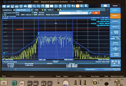
Vendor support was in full swing during an April 2022 inter-op event in Denver where cable operators converged to determine proper signaling operations between various CMTSs and CMs, and then observe OUDP signals being captured using newly built RF leakage meters. The effort was focused on assuring OFMDA configurations are able to be matched between the CMTS/R-PHY node and meter, and to witness that when OUDP parameters are aligned, accurate burst detection is possible. Multiple cable modem OFDMA signals were combined, then attenuated to support low, medium and high levels, and fed directly into the RF leakage meter antenna port. Once there was confirmation of OUDP lock, the meters were moved outside to a measured distance from a tuned transmit dipole antenna to again validate functionality by using the leakage detector’s antenna. Meters were then placed in vehicles that traveled different speeds past the transmit antenna.
“In the midst of chaos, there is also opportunity.”
— Sun Tzu
Conclusions
Entering the path to 10G means solving one of the RF leakage compliance challenges.
During the interoperability event witnesses were pleased to find out that functionality for high-split upstream RF leakage detection and measurement is indeed possible using near-production ready products. When cable operators align on specific needs, and then align product requirements with their vendor partners, the research and development focus is optimized to support faster speed to market.

Nick Segura,
Principal Engineer,
Charter Communications
Nick Segura is a Principal Engineer in the Network Technology Group — Outside Plant, and is based in Englewood, Colorado. He is responsible for architecting new technology solutions in the HFC realm to serve the company three to 10 years out. Nick has been active within the SCTE for over 30 years and currently serves on the Society’s Rocky Mountain Chapter board of directors.