High-Transmit in a High-Split Architecture: How to Tackle Issues Before they Fester
By Nick Segura
As cable operators upgrade their HFC networks on the path to 10G, implementing a high-split 204 MHz architecture is a viable solution. This prevalent approach can deliver solid results with proper planning and foresight, particularly around modem transmit levels. Upstream DOCSIS carrier configurations will necessitate OFDMA with updated measurement methods to support realistic pass/fail performance criteria. Keep reading to discover some of the top insightful operational best practices to support your companies’ standards, specifications, processes, and procedures (S-S-P-S) to avert trouble calls.
Carrier bandwidth reference—get it right
Measuring the power of an OFDMA carrier is unlike how we measure the more prevalent 6.4 MHz ATDMA carriers that have been in place for a long time. In following the DOCSIS spec we incorporate a constant power spectral density (PSD) using a reference bandwidth of 1.6 MHz. This allows us to derive a power level from any size bandwidth of OFDMA carrier—it is slick! Using basic math, we can convert the OFDMA power level to the same 6.4 MHz reference bandwidth used for ATDMA carriers. This enables an apples-to-apples comparison and supports applying the same target levels and pass/fail thresholds from current home health check processes. It also helps technicians grasp upstream tilt to avoid dynamic range window (DRW) violation messages.
Hand-held test equipment vendors provide an intelligent option to choose 6.4 MHz so techs can troubleshoot upstream RF levels more effectively. The same thinking applies to downstream for OFDM carriers of any size. Using a 6 MHz reference bandwidth mirrors digital video and DOCSIS SC-QAM signals. Understanding this concept is especially important for node and amplifier alignment in a 1.2 GHz and 1.8 GHz network design. In these systems, only OFDM carriers can be placed above 1 GHz. As a result, maintenance and network technicians should configure their test equipment to measure the power level of a 6 MHz slice of OFDM at a particular higher frequency when setting node and amplifier RF levels using a high-over-low level design methodology. An alternative is to insert a CW carrier at the highest design frequency and reference it for the “high” side.
Considerations for transmit thresholds, cause and effect
The need for greater upstream speed is apparent. However, care must be taken not exceed a modem’s maximum transmit capability. If a D3.1/D4.0 modem approaches or exceeds its RF output design capability, bonding all available upstream carriers becomes impossible. This leads to performance issues related to partial service statuses such as:
- TCS reduction—when the modem is in “protect mode” meaning it is appearing online but not actually using the upstream carrier.
- IUC reduction impaired
- Channel impaired
These issues often stem from exceeding maximum transmit power, low carrier-to-noise ratios, or excessive carrier-to-interference conflicts. To restore normal operations with full upstream carrier bonding, impairments must be cleared, and the modem reset. Transmit level and CNR and C/I headroom must be considered to allow for network fluctuations so stable carrier bonding can be maintained using the highest IUC modulation profile (note that 1024-QAM or higher is required to support gigabit symmetrical speed offerings in a 204 MHz high-split architecture).
Examples of a high-split 204 MHz maximum transmit OFDMA carrier capability can look like this:
- 44.25 dBmV (1.6 MHz reference bandwidth)—use this value when looking at the iCMTS/vCMTS command line interface.
- 50.27 dBmV (6.4 MHz reference bandwidth)—use this value in DOCSIS tools after incorporating a conversion factor of 6.02 dB to the above OFDMA carrier power).
Now apply upstream tilt
When carrying multiple upstream channels across a large bandwidth “tilt happens” … and depending on the type of coaxial cable and length, the headroom for the DRW may be used up before the total composite power (TCP) headroom and lead to partial service.
D3.1/D4.0 cable modems can accommodate upstream tilts as high as 12 dB. Tilt across each individual carrier is not defined in the spec, rather the focus of measure is from lower edge to upper edge of the upstream band. The longer the premises coaxial network, the higher the tilt (true for upstream and downstream); however, unlike downstream tilt the upstream band appears flat at the distribution amplifier, at the node, and at the CMTS, which is the design of long loop ALC.
When applying pre-equalization in a tilted upstream scenario the receive power at the burst receiver is reduced as more power is shifted into frequencies with higher insertion loss. The result is that the modem requires additional transmit power and service quality could be impacted if the modem is already at the top of its range.
Promoting all-carrier bond
When the upstream transmit channel set (TCS) increases from purposeful channel bonding, the total combined power increases. In sub-split architectures with ATDMA carriers existing modems transmitting near maximum power may not support additional required power when OFDMA channels are added. The limited transmit power budget of the modem could be exceeded by expanding the channel set.
When the TCP in the modem’s TCS exceeds its ability, the modem can lose lock with one or more of these upstream carriers and fall into a partial service state in order to maintain a TCP within its supported range. Ill effects of a modem that is ‘maxed out’ are total throughput reduction, and if utilizing OFDMA for OUDP leakage signaling, your over-the-air reference tag goes away.
Some ways to manage max transmit situations and foster full carrier bond is to reduce the CMTS upstream receive set point, reduce the TCS occupied bandwidth, and mitigate upstream path attenuation troubles. An operations best practice to support fewer partial service situations is to create a target threshold that is several dB below the modem’s maximum transmit capability.
How low can you go?
Well, it depends. There are several areas of “low” to define.
1. When speaking about low modem transmit power, DOCSIS 3.1/4.0 modems can transmit well below 30 dBmV and fully bonded in a noise-free environment; however, in real-world neighborhoods the noise funnel effect can be more severe. This is because when over-the-air interference ingresses into the coaxial network prior to the amplifier it will couple to the upstream DOCSIS signals at a less desirable ratio and could cause more damage. As an example, in a severe upstream noise storm event upstream carriers could incur more codeword errors with traffic from a modem transmitting at 28 dBmV compared to a modem transmitting at 42 dBmV.
If maintaining a higher transmit level to effectively reduce C/I, it is important to note that falling into an upstream partial service state related to max-transmit can be a worse situation to be in.
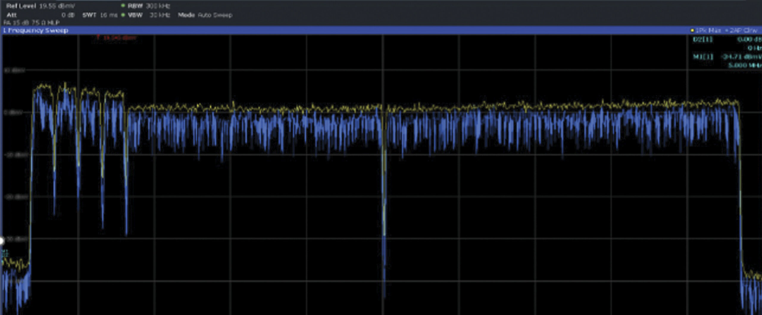
2. When speaking about the top of the upstream carriers as compared to the noise floor, or undesired ingress level, an observation can be made that (when using spectrum analysis) the height of DOCSIS carriers will lessen with increased total bandwidth bonded. This power spectral density phenomenon is not related to the first item above. You can expect the measured CNR or C/I radio to be the same for a modem transmitting at 28 dBmV versus a modem transmitting at 42 dBmV. DOCSIS channels with a similar CMTS target receive level will be reported identically across the same reference bandwidth (e.g., 6.4 MHz) although they ‘look’ lower. Common path distortion (CPD) is expected to be more prevalent as extended spectrum deployments ensue. The higher 1.2 GHz and soon 1.8 GHz downstream upper frequency limit, combined with the higher active output levels can ring back into the upstream path and show up as a higher noise floor. Therefore, maintaining decent C/I ratios is increasingly important.
Greater upstream loading requires lower RF levels in actives
Similar to the days when cable operators reoptimized 5 MHz to 42 MHz optical fiber paths to support an increased count of ATDMA channels, and supplemental OFDMA, they will again align nodes and amplifiers using a new lower RF port level design requirement to prevent gain stage distortions and analog laser clipping. Carrier to noise versus distortions has always been a delicate balance so be sure to design return path levels to achieve both the highest CNR, staying out of the thermal noise region, and maintain a comfortable noise power ratio clipping region—allowing for a little level variance.
Conclusion—success criteria
The message to the workforce does not have to change much because customer premises equipment has always come with limitations. Technicians can continue to follow current procedures to maintain optimal operating levels and keep an open dialogue with partner departments responsible for operating levels at the headend/hub, and node regardless of the architecture.
—
Images provided by author, Shutterstock
 Nick Segura,
Principal Engineer,
Charter Communications
Nick Segura is a Principal Engineer in the Network Technology Group—Outside Plant, and is based in Englewood, Colorado. He is responsible for architecting new technology solutions in the HFC realm to serve the company three to 10 years out. Nick has been active in SCTE for over 30 years and currently serves on the Society’s Rocky Mountain Chapter board of directors.