Where Did All the RF Go?
By Kraig Neese
A problem with testing an all R-PHY hub site
For those of us that have been around headends and hub sites for the last couple of decades, we know that we could connect a piece of equipment directly to the RF combiner of a node laser and upstream receiver to validate services. The tried and true “divide and conquer” approach to troubleshooting is etched into most of us who have had to deal with a node issue where RF or service quality comes into question. The ability to connect at the combiner in the hub site is an effective way to determine if a problem is north or south of the optical link for a node. Cutting the problem in half helps speed the troubleshooting and aids technical staff in determining the direction and locations to investigate. Do we focus on the field, or do we look more at the hub site? Not answering that question early on can lead to long delays in restoring customer services. As tried and true as this method is, what happens when there is no more RF in the hub site? What about new site builds that do not have any AM optics, every node is an RPD? The ability to divide and conquer gets a bit more complicated. How can a technician determine if there is an issue on the source CCAP or if the issue is due to a problem at the RPD miles from the hub site?
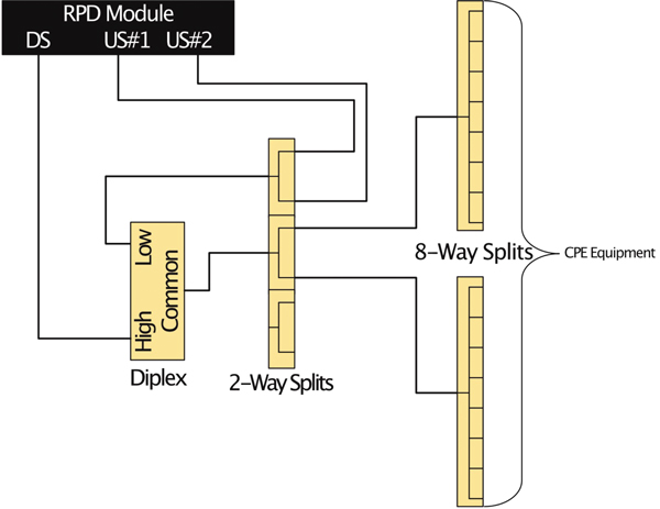
Figure 1. RF combining high level
We considered this problem at Cox during the initial launch of our R-PHY/DAA network. We determined that having a standardized test cabinet or rack was a necessary tooling expense. With numerous sites moving to R-PHY and new hubs built where there are only RPD nodes, we needed a better way. The solution was to have test racks in place as part of hub site buildouts before the first RPD went live. The cabinets would contain various CPE from different services. This gives our technicians the best possible chance to validate services before cutting a node over to R-PHY. Techs then needed the ability to check the health of services after a node joins the deployed RPD army. We considered a few options to squeeze what was needed and required into a rack. We also did not want to bloat the rack so much that it was a chore to use. There had to be additional RF test ports in the combining. A technician could connect a modem or set-top and test an out-of-ordinary scenario or connect a meter or analyzer for evaluation of the spectrum consumption — see Figure 1 for an example. Another requirement was the ability to see video remotely from the set-top boxes to validate video functions. Knowing that we could use our deployed DAA network to provision the RPD units in the rack and attach them to any CCAP DOCSIS or video service group in the hub site made remote control much more feasible.
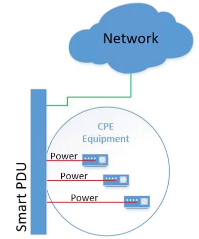
Figure 2. Smart PDU high level
Sometimes cable modems lose their way or a set-top is no longer happy and needs a power cycle. A remedy to physically pulling the power cord was to install smart PDU strips enabling remote power cycling of modems or set-tops — see Figure 2. The onsite technicians also wanted to be able to see the video of a set-top as they stood in front of the rack. A three screen rack-mounted monitor assembly that connected to some of the set-tops was provided as the solution. It did not take up much space at 2 RU and met the needs of our technicians. The list of needed equipment grew as we continued learning how to leverage this new test environment. After boiling down the absolute needs and then sprinkling in the higher wants, we began to deploy these racks in a repeatable fashion. We did this by creating a design playbook with company part numbers, standard rack elevation layout, RF connection schematic, and smart PDU power — see Figure 3. Now this standard configuration can be deployed anywhere by just about any of our inside plant technicians and engineers. Taking the “just get it done” approach and turning it into a guided process including getting billing system internal accounts for CPE properly provisioned, to making sure supply chain knew what and how much to send for a tech to build a rack proved to be quite the challenge. How can something so simple be so complex? In the end, that was the ultimate goal, to make something very tedious and complex become simple and relatively painless for a new site to deploy.
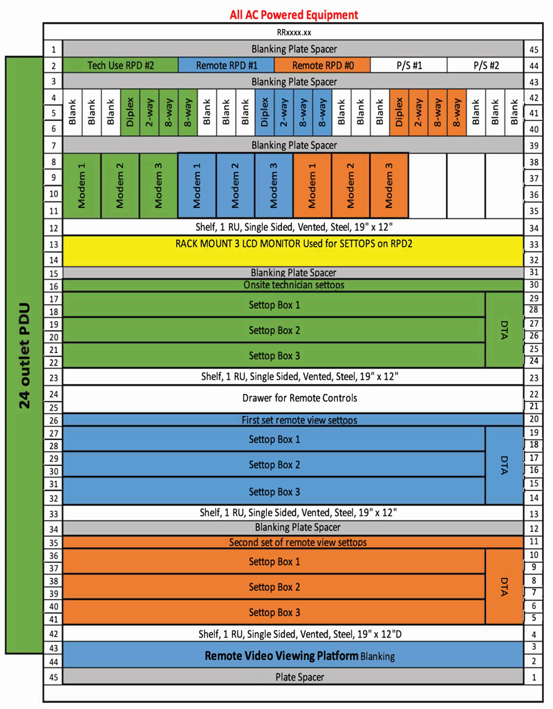
Figure 3. Rack layout
A remaining decision that had to be made was what RPD could be used in the new test rack? Hanging a full-sized, hardened node in a rack is a massive waste of space. Between the housing and the power supply needed to power them up you would consume half a rack. In addition to the wasted space, you would only get one RPD and at most two unique downstream service groups. This led to a more sensible solution using a 1 RU RPD shelf, yielding three distinct RPD units. Having three RPDs allowed for two sets of CPE that were solely remote controlled and one set of CPE that was for the hub site technician. This now allows for service validations and pre- or post-node cutover checks to an RPD. Having three RPD units also affords us the ability to have different tests and validations going on at the same time. Each RPD can be spread out and provisioned to existing service groups with other active nodes. Remote users could use two of the RPD units to determine if a problem could be replicated, levels be examined using our internal tooling for modem queries, or to determine if modems would even come online in a particular service group. The third RPD could be pointed to a new service group elsewhere for the onsite technician to do their own work for install pre-work or signing off that services are indeed working. Once again, the tried and true divide and conquer method was an option.
Though we cannot use the headend any longer to directly view the RF being generated by the RPD in the field, we can ensure that the RPD’s service group is working. We can ensure modems and video CPE do in fact come online and provide properly working services. In a world where multiple RPD nodes can share the same field aggregation devices and physical transport, we have enabled test RPDs that can now be moved to a suspect service group, remotely interact with some of the CPE, and then diagnose if there is a problem at the source or beyond. We can ensure that the general operation of video, data, tooling, and other functions are working correctly using the test RPD and racks.
These R-PHY test racks were intended to serve several related but distinct purposes:
- New CCAP core turnup validation
- Vetting of new service groups before RPD nodes are assigned to use them
- Reproduction of field issues in the hub site
As we installed more test racks, extra benefits came to light:
- We now have test RPD units across the country that we regularly use for testing new automation methods for provisioning
- Vetting video updates on a smaller scale before rolling out the change en masse
- Using the test racks to demonstrate to field engineers how modems will look when using a new service profile
The benefits of the new test racks continue to grow, making troubleshooting and maintaining an R-PHY environment more efficient. There is plenty more to learn as we grow our ability to monitor and troubleshoot these new DAA networks. We continue to push more functions to the remote edges of our networks and these new methods will need to adapt as we grow.
Kraig Neese
Cable Access Engineer,
Cox Communications, Inc.
]Kraig Neese is a Cable Access Engineer at Cox Communications. He has spent the last 22 years in the cable industry with Cox Communications. He spent his first 17.5 years in the Phoenix market, where he was involved in the various evolutions of DOCSIS platforms from DOCSIS 1.0 to the first launches of 3.0 and 3.1. He joined the Atlanta Access Engineering Team in 2018 and has been focused on supporting remote PHY on an operations and design level.