Understanding Band Splits In Two Way Networks
By Ron Hranac
The earliest cable networks were one-way — that is, signals could be transmitted only from the cable operator’s headend to the subscriber. Those one-way networks worked well for delivering primarily video services. When two-way technology was developed to support interactive services, it took advantage of the fact that radio frequency (RF) signals can travel either direction in coaxial cable, as well as in passive devices such as splitters, directional couplers, and taps.
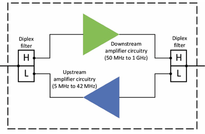
Things become much more challenging when amplifiers are thrown into the mix. A traditional amplifier circuit amplifies in one direction. The solution? Transmit downstream signals (cable company to subscriber) in one frequency range and upstream signals (subscriber to cable company) in a different frequency range. Amplifier housings can then include circuitry to separately amplify the signals traveling in different directions on different frequencies. Figure 1 shows a simplified block diagram of a two-way amplifier, in which the green triangle represents the circuitry to amplify downstream RF signals and the blue triangle represents the circuitry to amplify upstream RF signals.
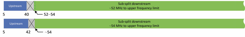
The majority of cable TV networks around the world were designed to use a sub-split band plan. A sub-split band plan is one that has most of the usable RF bandwidth allocated to downstream signal transmission. A small portion near the lower end of the usable spectrum is allocated to upstream transmission. Figure 2 shows an early sub-split band plan in which upstream signals were transmitted between 5 MHz and 30 MHz, and downstream signals were transmitted on frequencies above about 52 MHz. This was commonly known as a 30/52 split. (Note: The lowest downstream frequency for cable networks in North America and some other regions often is stated as 50 MHz, 52 MHz, or 54 MHz, even though CTA channel 2 starts at 54 MHz. The lowest usable frequency in the downstream spectrum varies somewhat among cable TV equipment manufacturers, but usually supports transmission of, say, narrowband downstream telemetry signals just below Ch. 2, between 50 MHz and 54 MHz.)

Over time the upstream spectrum’s upper frequency limit was increased from 30 MHz to as high as 40 MHz or 42 MHz, illustrated in Figure 3. Some regions of the world have used (and still use) other sub-split band plans. For example, a 65/85 split is common in Europe and elsewhere, in which the upstream spectrum is 5 MHz to 65 MHz, and the downstream spectrum starts at 85 MHz.
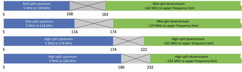
In years past the cable industry constructed some networks based upon mid-split and high-split band plans. Early mid-split and high-split band plans were typically used for institutional networks, municipal and educational applications, and a handful of residential applications. The upstream spectrum in a mid-split network was 5 MHz to 108~116 MHz, and the downstream spectrum started at 162~174 MHz. High-split networks used 5 MHz to 174~186 MHz for upstream operation; the downstream spectrum started at 222~232 MHz. The actual frequency splits in mid-split and high-split networks varied among cable TV amplifier manufacturers. See Figure 4.
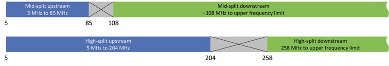
With the introduction of DOCSIS 3.1, mid-split and high-split band plans have been redefined. Today’s mid-split band plan uses 5 MHz to 85 MHz for upstream transmission, with the downstream starting at about 108 MHz (the actual downstream start frequency can be a few megahertz below 108 MHz — for instance, 105 MHz — and may vary among equipment manufacturers). The contemporary high-split band plan uses 5 MHz to 204 MHz for upstream transmission, with the downstream starting at 258 MHz. See Figure 5.
Cable network upper frequency limits have migrated to as high as 1 GHz over the years, with some networks being designed to support frequency usage to 1218 MHz (aka 1.2 GHz). Operation beyond 1.2 GHz is known as extended spectrum DOCSIS (ESD), with an upper frequency limit of 1794 MHz (aka 1.8 GHz) or greater. The new band plan for ESD networks is being called ultra-high-split (UHS). In a UHS band plan, the upstream starts at 5 MHz as before (some have suggested starting the upstream a little higher, say, at 10 MHz or so). A UHS upstream spectrum’s upper frequency limit can be 300 MHz, 396 MHz, 492 MHz, or 684 MHz. As of this writing, the start of the downstream spectrum in the various UHS splits is still being sorted out as practical diplex filter designs are evaluated.
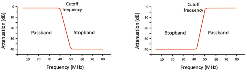
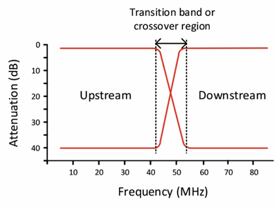
Speaking of diplex filters, those are critical components in two-way amplifiers. Referring back to Figure 1, note that the block diagram shows two diplex filters. The diplex filters, each of which is a combination of low-pass and high-pass filters (see Figures 6 and 7), keep the upstream and downstream frequency ranges separated so that the respective upstream and downstream amplifiers can operate properly and avoid interfering with each other. In practice, the upstream and downstream amplifier circuitry also includes additional low-pass and high-pass filters to further improve isolation. The combination of the pair of diplex filters and additional internal filtering helps improve overall amplifier stability and prevent problems such as oscillation.
As the industry expands frequency usage beyond 1.8 GHz, new band plans and upstream/downstream splits will be developed, too. There have been proposals to operate to 3 GHz or higher, taking advantage of the incredible capacity of our HFC networks. Another approach to two-way operation is full duplex (FDX) DOCSIS, in which a portion of the upstream and downstream spectrums overlap. The magic of upstream and downstream signals simultaneously occupying the same frequencies (without diplex filters!) is accomplished in part by technology known as echo cancellation, but FDX DOCSIS is a topic for another time.
 Ron Hranac
Technical Marketing Engineer,
Cisco Systems
rhranacj@cisco.com
Ron Hranac, a 47 year veteran of the cable industry, is Technical Marketing Engineer for Cisco’s Cable Access Business Unit. A Fellow Member of SCTE and co-founder and Associate Board Member of the organization’s Rocky Mountain Chapter, Ron was inducted into the Society’s Hall of Fame in 2010, is a co-recipient of the Chairman’s Award, an SCTE Member of the Year, and is a member of the Cable TV Pioneers Class of ’97. He received the Society’s Excellence in Standards award at Cable-Tec Expo 2016. He was recipient of the European Society for Broadband Professionals’ 2016 Tom Hall award for Outstanding Services to Broadband Engineering, and was named winner of the 2017 David Hall Award for Best Presentation. He has published hundreds of articles and papers, and has been a speaker at numerous international, national, regional, and local conferences and seminars.