Signal Leakage Patrolling at 700 MHz (Part Two)
By H. Mark Bowers
For background, please visit broadbandlibrary.com to refer to Part One of this article that appeared in the 2017 Winter Edition of Broadband Library. Part Two continues with screenshots at two additional field locations, plus summary and conclusion sections based on the results of all leakage detected.
Approximately 10 miles of plant were patrolled using a real-time spectrum analyzer (RTA) and two omni-directional antennas, measuring leakage on CTA channels 14, 15, 116, and 117 in the test system. A ‘diamond’ (magenta) marker usually notes the location of the visual carrier (if detected), and the ‘square’ (green) marker notes the aural carrier location.
Summary of Findings
- In the estimated nine to 10 miles of plant patrolled, I only located one leak where significant correlation seemed to exist between Ch. 14 and Ch. 117 (in Part One). In that singular instance, leakage at Ch. 14 just exceeded FCC limits while leakage at Ch. 117 was well within FCC limits. And only a single location was found where leakage exceeded FCC specifications at 750 MHz; all other leakage detected in either band was within specifications, and none of the remaining locations showed any degree of correlation between the two bands.
- I would estimate that in aerial plant sections, approx. 20% to 25% of all utility poles indicated evidence of very low-level leakage at Ch. 117. I did not attempt to determine the source of these leaks, as I did not have the time or a near-field probe during this patrol.
- Given the strong field strength from the local Verizon tower and relatively tight nature of the cable plant, my conclusion was that in this particular system; minor breaks in system integrity were more likely to create ingress problems for the cable operator, where ingress of LTE Band 13 spectral energy could impact Ch. 116 performance. In the case of high level leakage from the plant, it is possible that QAM carrier energy from Ch. 116 could affect cellular reception. Remember that (Verizon) LTE traffic utilizes OFDM with QPSK, 16-QAM or 64-QAM modulation; so in instances where discrete carriers egress (such as the un-modulated Ch. 117 visual analog carrier), the OFDM system will simply avoid the interfering energy of the visual carrier while utilizing the remaining spectrum. High-level QAM leakage is a different matter since the spectral energy of the QAM signal is spread evenly through the entire 6 MHz allocation slot.
- These findings generally agree with those found in previous papers by other authors, in that I found little correlation between leakage in the 108 MHz to 137 MHz spectrum as compared to leakage in the 700 MHz to 800 MHz range.
Conclusion
Finally, I believe this exercise raises the issue of how one is to perform accurate field strength measurements at higher LTE frequencies, where there is a low-level leak from the HFC plant (especially QAM), while LTE signal levels comprise the bulk of the spectral energy and overall field strength. It’s not realistic to expect field technicians to effectively utilize the RTA method I employed. The solution is that there are test equipment vendors that now offer leakage detection systems that can operate within this environment, and that provide for very low-level and highly accurate leakage measurements of QAM carriers.
In closing out this subject, remember the harmful interference clause in Part 76 always applies regardless of frequency band or leakage field strength. While the leakage levels found during this patrol were almost entirely within FCC specifications for the band of operation, any leakage found to be harmful to a licensed service in the area where it is detected must be resolved once the cable operator is aware of it.
—
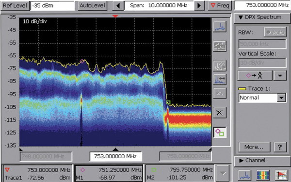
Screen Capture One. Moving on to a new location, Screenshot One illustrates a higher amplitude leak (as compared to the first location examined in Part One) from Ch. 117 underneath Verizon LTE OFDM traffic. RF levels are too low for an accurate field strength measurement; however visual carrier leakage was estimated at 86 microvolts/meter (μv/m). This leak is still within FCC emission limits at this frequency.
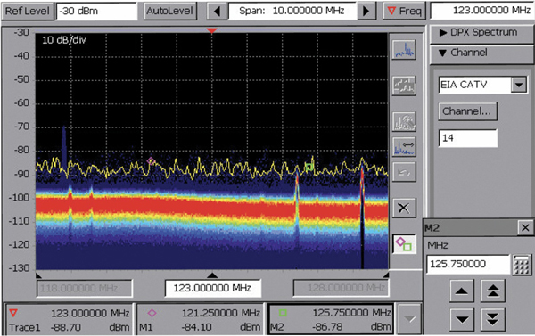
Screen Capture Two. Measuring at the same physical location, Screenshot Two shows no detectible leakage at Ch. 14, even though the leakage levels for Ch. 117 were moderate. This seemed to be the ‘norm’ at many locations; with low-level leaks detected at Ch. 117, while it was rare to detect correlating leakage in the 108 MHz to 137 MHz aeronautical band. Also note that there is a carrier at the right side of the screen that ‘appears’ to be the Ch. 15 visual carrier; however further inspection determined that it was an aeronautical beacon.
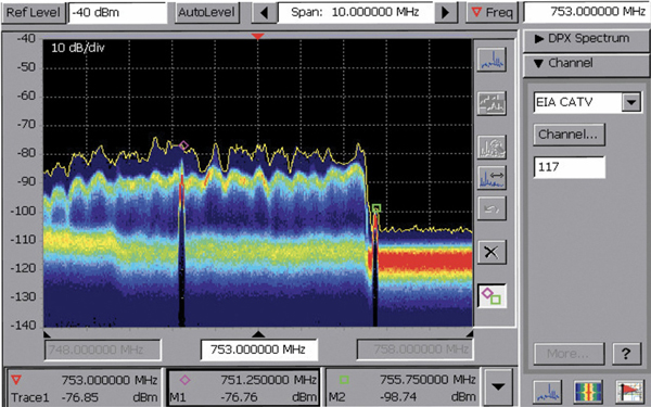
Screen Capture Three. At a final selected location for Part Two, Screenshot Three depicts the highest leakage level found at Ch. 117 during the plant patrol. Field strength measurements at Ch. 117 varied from 50 μv/m average to 306 μv/m peak. Leakage was highest at the rear of a house, but was also measured in the adjacent alley and at the front of the house. Internal/external house cabling or passives was the leakage source. Note also the rise in spectral energy in the lower portion of the LTE Band 13 spectrum, indicating leakage of the Ch. 116 QAM signal. Finally, peak leakage level exceeds FCC limits for this frequency.
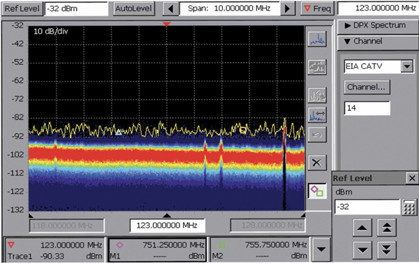
Screen Capture Four. Screenshot Four depicts Ch. 14 spectrum leakage at the same location and shows no visual carrier leakage (it would appear at the blue triangle marker). So, at this location the leakage mechanism is such that there is out-of-spec leakage at Ch. 117 while there is no detectible leakage at Ch. 14 or 15!
In Part Two of this article we’ll examine testing results from two other locations where correlation was found, and then draw some broad conclusions based on all the tests documented during that driveout.
 H. Mark Bowers,
Cablesoft Engineering, Inc.
Mark is VP of Engineering at Cablesoft Engineering, Inc. He has been involved in telephony since 1968 and the cable industry since 1973. His last industry position was VP of Corporate Engineering for Warner Cable Communications in Dublin, OH. Mark’s education includes the U.S. Naval Nuclear Engineering School, and BS and MS Degrees in Management of Technology. Mark is a member of the SCTE, the IEEE, and is a Senior Member and licensed Master Telecommunications Engineer with iNARTE.
Credit: Charts provided by author