CableLabs® Outage Reduction Taskforce Review — Plant Protection (Part Two)
By H. Mark Bowers
In August 1992 in conjunction with a CableLabs conference on this subject, the Outage Reduction Task Force issued its initial findings and recommendations from the first four subcommittees. Each area of outage reduction research had a separate subcommittee, with the final report a compilation of the research and recommendations of all subcommittees. Many subcommittee recommendations are no longer applicable to the modern HFC plant; however the subcommittee report on Outside Plant and Headend Protection contains information and recommendations that are still important for modern HFC plant operation.
In Part One (Fall 2019 printed and on-line editions of Broadband Library; republished in the Winter 2019 on-line edition) I outlined the overall purview of this task force including subject matter and testing methods developed. In Part Two we now review specific subcommittee recommendations. The complete report for Chapter IV comprised some 27 pages; however my column only summarizes their findings and recommendations. If you have not read Part One of this column, I recommend that you do so before proceeding.
Summary of Plant Voltage and Current Protection Recommendations
- The subcommittee recommended the adoption of the ANSI/IEEE C62.41-1980 Category B2 (6,000 volt, 3,000 ampere) test standard for manufacturers and cable operators to determine the effectiveness of surge suppression devices. See Figures 1 and 2 in my previous column at broadbandlibrary.com. The task force recommended the use of this test in simulated plant configurations, and further recommended that cable operators require equipment manufacturers to certify that their equipment meets or exceeds recommended performance criteria set forth in their report.
- It was the task force’s opinion that deployment of surge suppression equipment that meets or exceeds recommended performance criteria, in conjunction with adopting their recommended fusing policy, should significantly reduce limited-duration over-voltage and over-current related outages.
Subcommittee recommendations were based on research, computer analysis, surge device testing, and successful field trial results. The recommendation section of their report is divided into five categories:
- Surge Voltage Protection
- Excessive Current Protection
- Grounding & Bonding
- The Headend
- Final Summary
Their Grounding & Bonding category is the most detailed.
The Surge Voltage Protection category is divided into three sections: New Equipment, Outside Plant and Headend, and Existing Actives.
- For New Equipment purchases, they recommended that all actives be certified to pass at least five 6,000 volt impulses of the ANSI/IEEE adopted test, and that the vendor provide detailed testing documentation upon request.
- The Outside Plant and Headend protection assumed the introduction of new surge protective devices such as an AC crowbar into the outside plant. The vendor should certify that the operating characteristics of the surge protection device(s) will not materially change when subjected to a minimum of 10 voltage surges (using the ANSI/IEEE test) spaced one millisecond apart. And again, that the vendor provide detailed testing documentation upon request.
- Finally, for Existing Actives their recommendations were limited to network locations where there were reliability problems, as it was deemed unrealistic to apply their recommendations across an entire operational network. Recommendations in this section include the type of protective devices that should be installed along with the removal of other surge protection device types if present.
The Excessive Current Protection category addresses New and Existing Equipment in the outside plant. Recommendations include fuse/circuit breaker type and current limits to be utilized at the main AC supply, fiber node and trunk stations, feeder lines, and locations/devices that utilize fuse(s) for AC power routing. Whether a fuse or circuit breaker is used, they should always be of the time delay (slow-blow) type. Fast blow fuses and/or circuit breakers are not appropriate for excessive current protection.
As already mentioned, the Grounding and Bonding category is the largest and contains a great deal of information including a summary of issues, National Electrical Safety Code (NESC) requirements, the common grounded electrode system, recommended bond/ground placement, calculations for various scenarios including longitudinal sheath current (LSC) conditions, and pitfalls to avoid including the placement of too many bonds and/or grounds.
The Headend category is divided into three sections: Surge Protection, Grounding and Bonding, and Standby Power.
Devices identified for surge (voltage) protection include:
- Incoming AC power line
- Telephone/data lines
- AC feed from backup generator
- Over-the-air antenna downleads
- Rotor control lines for search antenna (if applicable)
- TVRO feeds
- Two-way radio, repeater, and cellular antennas
- Tower lighting wiring
- Microwave waveguide(s) (if applicable)
- Broadcast, translator or MMDS transmitter feedlines
- Incoming fiber optic or hub interconnects
- Outbound trunk and/or feeder cables
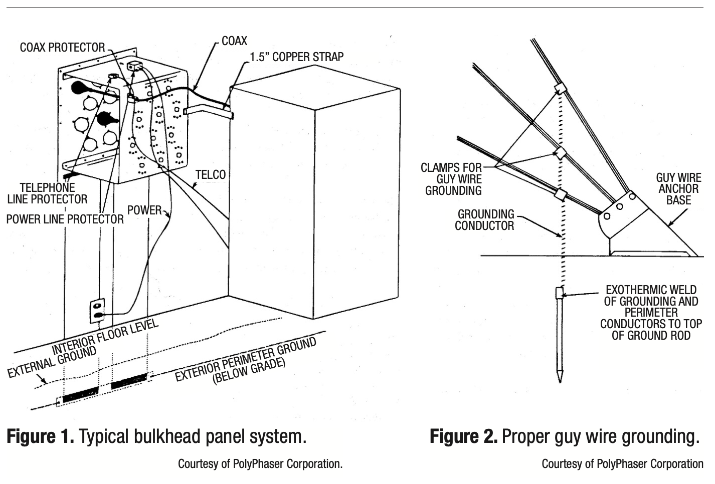
The Surge Protection section includes a 1990s illustration of a transient suppression plate (bulkhead) recommended as a surge/transient shock absorber. This plate must be tied to the common grounded electrode system as well as the outer shields of all incoming/outgoing cables. Center conductor protection for these same cables is most effective as a sub-chassis or sub-bulkhead attached to the inside of the primary bulkhead. Telephone/data, power and other line protectors also should be mounted on this sub-chassis. See Figure 1.
A discussion of proper headend Grounding and Bonding follows including detail regarding the common grounded electrode system. The concept of common-point grounding to form an equal potential grounding system at the headend is very important, especially with regard to lightning protection. While complete protection from a direct lightning strike is not achievable, high quality grounding/bonding practices can produce excellent results.
A description of the proper method for tower and guy wire grounding follows. This includes the proper placement of ground rods and the proper method for attaching the grounding wire to the tower or guy wire. The use of exothermic welds (rather than mechanical ground clamps) is recommended for some applications but should be avoided in others. See Figure 2 as an example.
Final headend recommendations address backup power. The typical solution to loss of commercial power at the headend is to provide backup power utilizing a standby generator and automatic transfer switch. While effective as a long time duration solution for complete power loss; there is typically a brief time period, typically 10 to 30 seconds, between the loss of commercial power and the availability of generator electrical power due to the startup cycle. The task force recommended that an uninterruptible power supply (UPS) be incorporated in the headend to maintain operation during this generator startup and transfer switch time period.
Their report concludes with an Outside Plant Protection Summary. The reduction of outages in the cable network (whether 1992 or 2020) is a goal that should be on every operator’s agenda. Operators should understand how the subscriber views an outage and have accurate outage tracking procedures in place. And one of the most effective ways to achieve outage reduction is through proper outside plant and headend protection.
The deployment of solid-state surge protection devices that meet or exceed the guidelines presented in their report plus implementation of their recommended fusing practices can achieve a significant reduction in outages. Recommendations for headend protection should be implemented since headend problems often affect all subscribers simultaneously.
Although not directly related to plant protection, headend and system maintenance practices that result in system downtime on one or more channels need to be coordinated and scheduled in a manner that will cause the least disruption to customers, particularly during prime viewing times. Careful scheduling of maintenance outages should be a part of every system’s outage reduction practices.
In conclusion, I’d like to note that the personnel who comprised this subcommittee represented some of the most knowledgeable industry engineers on this subject at that time. Thirty years later, the collective knowledge and recommendations captured by these engineers are worthy of careful review. The cable television industry owes a debt of gratitude to CableLabs and all subcommittee members who spent {the} hundreds of hours necessary to discuss, review and assemble these recommendations.
The original and complete “Outage Reduction” document was provided to CableLabs members in a gray three-ring binder back in the early 1990s. The first four chapters on “Outage Reduction” were also published in the December 1992 through March 1993 issues of Communications Technology magazine. Check your bookshelves to see if you still have copies, or contact CableLabs (if you’re a member company) to determine availability.
 H. Mark Bowers,
Cablesoft Engineering, Inc.
Mark is VP of Engineering at Cablesoft Engineering, Inc. He has been involved in telephony since 1968 and the cable industry since 1973. His last industry position was VP of Corporate Engineering for Warner Cable Communications in Dublin, OH. Mark’s education includes the U.S. Naval Nuclear Engineering School, and BS and MS Degrees in Management of Technology. Mark is a member of SCTE•ISBE, IEEE, and is a Senior Member and licensed Master Telecommunications Engineer with iNARTE.
Credit: Charts provided by author