CableLabs® Outage Reduction Taskforce Review — Plant Protection
By H. Mark Bowers
During 1991 and 1992, the CableLabs’ Outage Reduction Task Force expended considerable effort and research into finding practical solutions to reducing cable system outages. The final report was issued in August 1992 in conjunction with a CableLabs conference on this subject. Each area of investigation had a separate subcommittee, and the final report was a compilation of the research and recommendations from each subcommittee.
- Chapter I provided an agreed-upon definition of an outage, customer acceptability, and an outage detection and tracking specification.
- Chapter II discussed reliability modeling of cable systems, and included a spreadsheet (issued in Lotus 123) that could be used as a tool for network reliability analysis (the program calculates overall network availability).
- Chapter III reviewed plant powering techniques, including reducing power supply cascades, hardened trunk techniques, understanding and working with the local electric utility, and optimal application of standby powering.
- Chapter IV focused on outside plant and headend protection. The plant protection subcommittee reviewed equipment fusing, surge protection, bonding/grounding practices, and issued a number of recommendations that applied to the headend and outside plant.
- The remaining chapters included Chapter V — Service Restoration; Chapter VI — Cable TV System Power Supplies; and Chapter VII — Power Grid Interconnection Optimization.
Almost 30 years later much of the full report information is dated and no longer applies to the modern HFC network. For example, I chaired the Chapter III subcommittee on Plant Powering. Although our recommendations were pertinent and helpful at that time, the continued introduction of fiber into the cable plant model along with drastically reduced node size and amplifier cascades have rendered many of our recommendations unnecessary. Much of the work conducted by the Chapter IV subcommittee on Plant Protection, however, remains informative and applicable.
The complete Chapter IV is 27 pages in length. In this summary, I’m choosing several sections of the report that seem still pertinent to me, however, my two-part article (this issue and Winter 2019) summarizes only a portion of their total findings.
Summary
The scope of Chapter IV addressed the following areas:
- System reliability overview.
- Common practices for surge and over-current protection.
- Surge protection testing techniques.
- Recommendations for over-voltage and over-current protection in the outside plant.
- Recommended bonding and grounding practices in the outside plant.
- Recommended grounding and bonding techniques for the headend, including recommendations for the proper grounding of tower guy wires.
System reliability
Overall network reliability depends directly on the reliability of the discrete components that comprise the network in both the headend and outside plant. Reliability analysis in the early ’90s indicated that (cascaded) equipment failure rates in totalmust be ≤ 7% per year to achieve outage performance acceptable to subscribers, and this level includes blown fuses, cut cables, and equipment failures.
Effective protection from excessive voltages and currents is critical to achieving this rate. Of the many mechanisms that cause outages, these two are among the easiest to prevent. Excessive voltage conditions are typically of extremely limited duration; for example, surges or transients due to lightning or electric utility load switching. Excessive current is created by short circuit conditions that are usually of longer duration. Typical causes are a short between the coaxial cable sheath and center conductor due to maintenance activity or electronic component failure, or the presence of longitudinal sheath currents (see my 2019 Summer Broadband Librarycolumn). The full CableLabs report evaluates a number of deficiencies in voltage and current protection practicesthat often contribute to reduced system reliability.
Common practices
At the time this research was conducted, commonly accepted over-voltage and over-current protection practices were found to be causing more problems than they solved, either because of incorrect application or deficiencies with those practices and components. The task force targeted the following issues:
- Surges or transients blow fuses resulting in nuisance fuse blowing. Fuses are over-current protection devices, and are not intended to protect from voltage transients or surges.
- The life of some surge protection devices internalto an amplifier is considerably less than total amplifier lifetime, with no practical means to detect internal device failure.
- Some surge protection devices have questionable ability to handle a series of voltage surges; for example, five to 10 surges in less than one second.
- Fast-blow fusing is sometimes employed for protection against long-duration high current conditions. Long-duration high current or temporary inrush conditions should be protected by time-delay (slow-blow) fusing.
- The excessive use of fuses, for example, for routing power. Many active and passive components in cable systems provide fusible links for power routing. Excessive use of fuses in actives or passives create additional nuisance fuse blowing.
All of this begs the question “What methods work the best?” Since CableLabs does not endorse or recommend specific products or manufacturers, the outage reduction task force set out to establish a recommended practice that can be used as a guideline by cable operators and equipment manufacturers. Their recommendation (detailed in the full report) was two-fold, with surge protection addressed first and fusing guidelines second.
Surge protection
Different types of surge protection are available to the cable industry, each suited for a specific application and each varying in its effectiveness for the intended application. As part of the development of a recommended practice for surge protection, CableLabs commissioned independent laboratory testing of several of the most commonly used protection devices; including metal oxide varistors (MOVs), gas-filled surge arrestors, silicon avalanche diodes, and crowbar devices (AC or DC circuits that incorporate SCRs or TRIACs in a crowbar configuration).
Metal oxide varistors and silicon avalanche diodes are basically voltage limiting devices, while gas-filled surge arrestors and crowbar devices operate by clamping circuit voltage peaks to a reduced value (AC crowbar devices usually clamp to ground potential once triggered).
Laboratory testing was accomplished to establish a repeatable measurement procedure that was representative of conditions that might be experienced in outside plant operation and that could be used by operators and/or manufacturers to compare the relative effectiveness of various surge protection techniques. During lab testing, the following two test setups were employed.
Test setup #1
The test samples were exposed to a series of test impulses to verify their capability to withstand the impulses. See Figure 1. Each sample was subjected to a series of 6,000 volt impulses at 3,000 amperes. The impulse is described in ANSI/IEEE Standard C62.41-1980 and replicates a lightning induced over-voltage surge. This test checked clamping capability and survivability. Depending on survival, each sample was tested with up to five impulses.
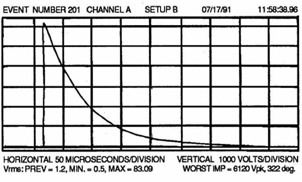
Figure 1.Impulse described in ANSI/IEEE Standard C62.41-1980
A KeyTek 587 Plus test set was used to generate the surge voltage shown in Figure 1. The surge impulse was AC coupled and injected through an AC port in a power inserter to replicate a surge condition created in the field when a lightning-induced surge couples onto coaxial cable. A Dranetz Model 658 power monitor recorded clamping voltage and surge current, and a simple rectified load drawing 13 amperes completed the test jig.
Crowbar clamping devices were subjected to a different impulse, one of lower repetitive energy as shown in Figure 2. The test impulse did not place a great deal of stress on the protector (impulse energy was approximately 10 millijoules), but did force the protector to continuously conduct and carry the maximum current delivered by a 60 VAC ferroresonant power supply. This test condition is a modification of UL497A (over-current stress test) and is intended to replicate a condition that might force the protector to turn on repetitively — for example under longitudinal sheath current conditions. Each test lasted 10 seconds, and was repeated five times at 10 second intervals. The test verified that heat buildup during conduction did not degrade or destroy the protector.
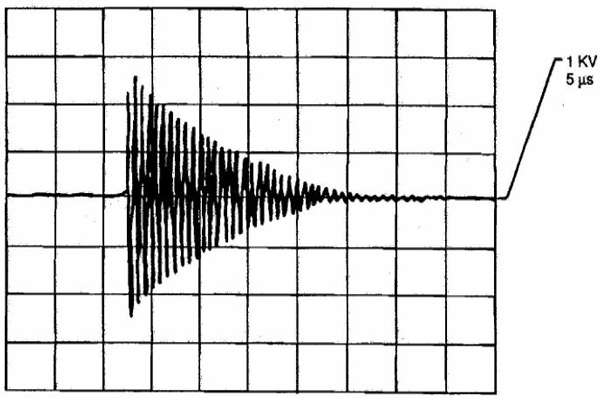
Figure 2.Voltage pulse used to test voltage clamping devices
In Part Two (Winter 2019 Edition of Broadband Library)we will review the results of these tests along with subcommittee recommendations for optimal surge protection methods (components and their application).
The original and complete “Outage Reduction” documentwas provided to CableLabs members in a gray three-ring binder back in the early 1990s. The first four chapters of “Outage Reduction” also were published in the December 1992 through March 1993 issues of Communications Technologymagazine. Check your bookshelves to see if you still have copies of either, or contact CableLabs (if you’re a member company) to find out about availability of “Outage Reduction.”
 H. Mark Bowers,
Cablesoft Engineering, Inc.
Mark is VP of Engineering at Cablesoft Engineering, Inc. He has been involved in telephony since 1968 and the cable industry since 1973. His last industry position was VP of Corporate Engineering for Warner Cable Communications in Dublin, OH. Mark’s education includes the U.S. Naval Nuclear Engineering School, and BS and MS Degrees in Management of Technology. Mark is a member of the SCTE, the IEEE, and is a Senior Member and licensed Master Telecommunications Engineer with iNARTE.
Credit: Charts provided by author