Extended Spectrum Beyond 1.2 GHz
The Odds of a Predicted Outcome are Favorable
By Nick Segura
Delightful lessons learned from past bandwidth expansion projects allowed operators to develop best practices which support anticipating and avoiding obstacles for future projects such as extended spectrum (ES) upgrades in the not so distant future.
When we inform our industry HFC subject matter experts that ES upgrade projects are expected to involve drop-in amplifiers taking advantage of existing amplifier and tap spacing, these experts will only partially believe us and will resort to their tribal knowledge and historic wisdom from similar projects in their past to avoid potholes and other familiar obstacles.
This is why we must begin talking about predicted pain-points now so as to avoid time lost from mistakes we’ve already made in the past. With our eyes wide open we already understand there will be an occasional full upgrade required as design-stretched locations are uncovered.
Gotchas from the past
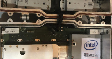
The fundamental mechanical aspects of an ES upgrade will relate to HFC powering and splicing techniques for the anticipated replacement of actives and passives to include where we start and where we end. Clearly the need for additional electric power in an HFC power boundary will increase as per-active device consumption is required due to the additional total composite power needed by RPDs and amplifiers to support the added bandwidth, and we will need to be cognizant of today’s and tomorrow’s wireless radios which draw electricity. What happens first? It’s pretty clear that RF level setup and performance testing can only occur after routers and optics are replaced, after RPDs are set into place and after power boundaries are re-designed and taps upgraded. The beauty of this bandwidth expansion is that we can count on our industry’s coaxial splicing teams who have previously mastered an understanding of the installations and replacements of active and passive devices when size and space restrictions are so common. The goal is to avoid kinking cables and blocking seizure screws and test ports in various aerial and underground applications — nothing new here. However, what engineering will need to inform them is that hardline pin connectors, if not left at an exact design length, will affect frequency response and if factory pin connectors are trimmed it may come with S-parameter penalties. Another advantage of an upgrade is that taps are already in place today and have signal flowing through them making it more difficult to find a ‘backwards taps’ after resplice.

The fundamental electrical aspects of an ES upgrade relate to adequate RF level and signal performance born directly out of the precious balance between amplifier carrier-to-noise and distortions, power level, and tilt — respect new aspects of upstream tilt — it is real! We cannot assume today’s technicians will know or understand what trouble may be associated with it, nor can they use signal level meters in an identical fashion. If a single downstream linear tilt is chosen it could be as high as 24 dB and the dynamic range of signal level meters may be insufficient. Because our upgrade teams will already be familiar with most aspects of ES and what equipment and tools are needed, they will hit the ground running as “it’s another bandwidth expansion project.”
Connectors and cable
Remember, measure twice and cut once! Especially now as we approach carriage of 3 GHz frequencies the F-connector will look different and the importance of craftsmanship for optimum connectivity at 3 GHz will never be so important. If you’re like me, I favor the F-81 barrel type that incorporates multiple fingers because I expect greater mechanical coverage to mean better frequency and current flow. Some coaxial connector manufacturers are designing products with enhanced frequency performance to allow for additional operational margin, and they’re anticipating the reuse of the compression tools used in the field today to save us money. Supreme craftsmanship will continue to make or break our efforts in a broadband spectrum offering which means we’ll need to be diligent in training, quality control inspections and through examining and removing worn out tools from service at first sign of wear.
The art of fidelity
Achieving optimum MER will require us all to continue determining the fine balance between CNR and CIN (with digital distortions) and each operator will need to work closely with their vendor partners to choose the best design and performance specs for their application — similar to how they have in the past. If any of your cable systems were keen to take advantage of increased QAM RF level headroom realized after the removal of all analog carriers, then maintaining similar levels out of the tap ports will need to be a definite conversation with your RPD and amplifier vendor due to the increased total composite power required for adding the band above 1.2 GHz. Fortunately, new premises designs utilizing a single DOCSIS gateway device will allow for lower RF levels out of the tap, and this simplifies installations when only four F connectors are required. To clarify, lower RF levels at the tap may sound upsetting at first until you realize an optional design where premises splitters are removed and where wireless signal distribution is the primary method for distributing all services. Advances for greater dynamic signal ranges in new DOCSIS 4.0 modems will mitigate certain scenarios where high-tilt from short drops on a high value tap, or high-tilt from long drops on a low value tap, are sometimes problematic. In addition, substantial MER increases, compliments of DAA remote PHY, will provide an added layer of performance margin and signal resiliency making ES highly viable and competitive.
Required groundwork
Conformance testing to a specific standard and specification is mandatory to determine whether a product or system can provide optimum performance and interoperate with existing systems. We are fortunate to have CableLabs and SCTE•ISBE fully engaged in this space and they are extremely busy lining up our industry for success.
Our seasoned managers and technicians certainly understand anomalous corner cases, and some even claim to know where they are; There will likely be plant and premises applications needing 3 GHz equalizers, inline conditioners and even coaxial filters. These special scenarios will need to be brought up within the design and engineering groups along with distinctive product needs like subscriber drop power inserters, backhaul, MoCA network adaptations and even special terminations which may appear low-risk today.
Regulations governing performance are understood by operators today, especially after we moved to an all-digital world. Besides understanding SCTE-40 and DOCSIS requirements, what else might be required? High-split systems will require some thought on how we continue to monitor and repair signal leakage, and because of the benefits that come with focus on cable isolation we will be smart to increase the focus on enhanced monitoring for signal leakage and ingress whether FCC rules apply or not.
Lastly, let’s reinvestigate and define what a technician’s need for test equipment is. We’ll not get away without having a form of RF level and health performance measurement — to include PNM toolsets as we seek to benchmark and maintain new spectrum in the ES future. Our technical operations centers will need the same considerations with additional remote monitoring upgrades to proactively identify impairments in diplex filters and end-of-spectrum rolloffs for active ES frequencies. Through preventive maintenance programs, which leverage PNM, our field operations teams have uncovered numerous plant and premises issues prior to them impacting our customers’ service. PNM is standard practice in all systems capable of up to 1.0 GHz today and it will be even more primary as we operate upgraded extended spectrum plants tomorrow in support of superior signal delivery and signal reliability. This helps us fend off competition and assure our customer products work as designed — and work all of the time.
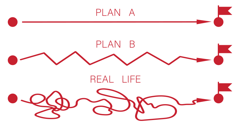
Getting to ES 1.8 GHz and 3.0 GHz could be smooth or bumpy, it’s our choice.
 Nick Segura,
Principal Engineer,
Charter Communications
Nick.Segura@charter.com
Nick Segura is a Principal Engineer in the Infrastructure Architecture & Engineering OSP group in Englewood, Colorado. He joined Charter in 2003 to assemble their Technical Quality Assurance Program, has served as Director of Technical Operations and is now responsible for developing new technology solutions in the RF realm that are reliable, simple and cost effective for the outside plant. Nick has been active within the SCTE•ISBE for over 28 years and currently serves on the Rocky Mountain Chapter board of directors.
Images from Shutterstock