Return Loss
By Ron Hranac
The coaxial cable portion of our networks has long been designed and built to have a nominal impedance of 75 ohms. The word “nominal” is used to describe the impedance, because it’s pretty much impossible for the impedance to be exactly 75 ohms, especially across a wide frequency range. Another way to look at this is to understand that all connectors, passive and active devices, and even the coaxial cable itself represent an impedance mismatch of some sort. The question is just how severe is each impedance mismatch?
There are several ways to characterize impedance mismatches, among them a parameter known as return loss (quick side note: “return loss” as discussed here has nothing to do with the attenuation or loss in the upstream spectrum). What’s return loss? The IEEE Standard Dictionary of Electrical and Electronic Terms, Fourth Edition defines return loss as “the ratio in decibels of the power incident upon the discontinuity to the power reflected from the discontinuity.” The McGraw-Hill Dictionary of Scientific and Technical Terms, Fourth Edition defines it as “1.The difference between the power incident upon a discontinuity in a transmission system and the power reflected from the discontinuity. 2. The ratio in decibels of the power incident upon a discontinuity to the power reflected from the discontinuity.”
When the impedances of a signal source, a transmission line such as coax, and a load (e.g., amplifier, tap or other passive, modem, terminator, etc.) are identical, all of the incident power — except that lost to attenuation in the transmission line — is completely absorbed by the load. When an impedance mismatch exists, some of the incident power is reflected by the impedance mismatch back toward the source. The reflected wave interacts with the incident wave to produce what are called standing waves in the transmission line. If you’ve ever swept outside plant, you know that an impedance mismatch such as an unterminated cable causes standing waves or amplitude ripple in the frequency response.
Here’s a closer look at some of the parameters used to characterize the severity of an impedance mismatch.
Reflection coefficient is the ratio of reflected voltage Ereflected to incident voltage Eincident, and is represented by the symbol Γ (gamma) or ρ (rho). The value of Γ can range from 0 for a reflectionless load, to 1 for a completely reflecting load (short circuit, open circuit, or pure reactance). Mathematically, reflection coefficient is
Γ = Ereflected/Eincident
Voltage standing wave ratio (VSWR) is represented by the symbol r. According to The ARRL Handbook for Radio Communications, “For a lossless transmission line at least ¼ λ long, the ratio of the maximum peak voltage anywhere on the line to the minimum value anywhere along the line is defined as the voltage standing wave ratio.”
The relationship between reflection coefficient and VSWR is
r = (1 + |Γ|)/(1 – |Γ|)
and
|Γ| = (r – 1)/(r + 1)
R is the symbol for return loss, which as previously discussed is the ratio, in decibels, of incident power Pincident to reflected power Preflected, or incident voltage to reflected voltage, described in the following two formulas.
R = 10log10(Pincident/Preflected)
and
R = 20log10(Eincident/Ereflected)
A couple other formulas that describe return loss are
R = 20log10(1/|Γ|)
and
R = –20log10(r – 1)/(r + 1)
Note the minus sign in front of the “20” in the last formula. If the minus sign is not included, the answer will be a negative number, which is incorrect for return loss. That said, some references wrongly state return loss in negative numbers. What’s going on? The confusion generally arises because the decibel representation of reflection coefficient is a negative number, but return loss is a positive number, as long as Preflected < Pincident.
What, then, is a good return loss value? Generally speaking, a higher number is better. In a perfect world a source and load would have exactly the same impedance, so all of the incident power would be absorbed by the load and the return loss would be infinite (∞). In the real world, some typical values of return loss are 16 dB to 18 dB for amplifiers, 18 dB or thereabouts for line passives such as taps, and 30 dB for hardline connectors.
To further clarify the concept of return loss, consider the following example.
Assume the incident power at the input to a tap is 30 dBmV (13.333333 microwatts), and the reflected power from that same tap is 12 dBmV (0.211319 microwatt). The return loss in this instance is the difference between incident and reflected power, or 30 dBmV – 12 dBmV = 18 dB. This example shows that the reflected power (12 dBmV) is 18 dB less than the incident power (30 dBmV).
The previous example can be validated by plugging the power levels in microwatts (be sure to use the same units in the numerator and denominator) into the formula R = 10log10(Pincident/Preflected):
R = 10log10 (13.333333/0.211319)
R = 10 * log10 (63.10)
R = 10 * 1.80
R = 18 dB
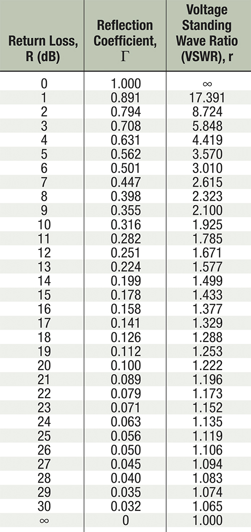
Several metrics are used to characterize the severity of impedance mismatches. The cable industry most often uses return loss, which fits in nicely with our use of the decibel for various other measurements. As mentioned previously, the higher the return loss number, the better.
The accompanying table includes several values of return loss, and corresponding values of reflection coefficient and VSWR.
How Does an Impedance Mismatch Cause a Reflection?
The following explanation is paraphrased or excerpted from information in the books Reflections by M. Walter Maxwell, published by the American Radio Relay League; and Handbook of Coaxial Microwave Measurements, originally published by GenRad, Inc. and reprinted by Gilbert Engineering (now Corning-Gilbert).
The characteristic impedance Zc of a transmission line such as coaxial cable is defined as the ratio of voltage E to current I in a traveling wave: E/I = Zc ohms. For this discussion, assume the transmission line is lossless; the superscripts “+” and “–” are used here to represent incident and reflected traveling waves.
As an incident wave leaves a source, it “sees” the characteristic impedance Zc of the transmission line as a resistive load. The incident wave is an electromagnetic signal, with half of its energy in the electric field (because of voltage) and half in the magnetic field (because of current). The incident voltage E+ and incident current I+, which are constant along the transmission line, are in phase because Zc is resistive. As the incident wave travels along the transmission line, the ratio E+/I+ in the line equals the line’s characteristic impedance Zc.
The ratio of total voltage to total current at the load equals the terminating impedance: Et/It = Zt. If the incident wave is the only wave on the transmission line, then Et = E+ and It = I+. Under these conditions, the load impedance Zt and transmission line impedance Zc are equal, and all incident power is absorbed by the load.
Consider a scenario in which a feeder cable is unterminated at the end-of-line, resulting in an open circuit. There is no current in an open circuit, so the magnetic field at the open circuit collapses. The collapsing magnetic field creates a new electric field with the same energy as the original magnetic field. The new electric field adds in phase with the original electric field, making the voltage at the open circuit twice the voltage of the incident wave. This represents the development of a standing wave: current is minimum, and voltage is maximum.
The higher voltage at the open circuit and its electric field causes a reflected voltage wave E– to start traveling back towards the source. The new reflected wave is the same magnitude as the original incident wave (no energy was absorbed by the open circuit), so reflection coefficient Γ = E–/E+ = 1. Return loss is 0 dB because there is no difference between the incident and reflected voltages; that is, the open circuit results in 100% reflection.
The motion of the new reflected electric field results in a new magnetic field whose phase is opposite that of the original magnetic field. The new magnetic field’s motion causes current to increase to the same magnitude as the original, resulting in a reflected current wave I– with the opposite polarity and traveling in the opposite direction of the incident current I+. Looking at just the reflected wave, E–/I– = –Zc. The minus sign in front of Zc simply indicates a reflected wave traveling back toward the source.
The total voltage or current at the load at any given point in time is the sum of voltages or currents of the incident and reflected waves: Et = E+ + E– and It = I+ + I–. The reflected voltage is in phase with the incident voltage because the sum of the two at the open circuit load is double the original incident voltage — they add because they are in phase. The reflected current is out of phase with the incident current because the sum of the two is zero at the open circuit — they cancel because they are out of phase.
 Ron Hranac
Technical Leader,
Cisco Systems
Ron Hranac, a 44-year veteran of the cable industry, is Technical Leader for Cisco’s Cable Access Business Unit. A Fellow Member of SCTE, Ron was inducted into the Society’s Hall of Fame in 2010, is a co-recipient of the Chairman’s Award, an SCTE Member of the Year, and is a member of the Cable TV Pioneers Class of ’97. He received the Society’s Excellence in Standards award at Cable-Tec Expo 2016. He has published hundreds of articles and papers, and has been a speaker at numerous international, national, regional, and local conferences and seminars.