A Word Paints a Thousand Pictures
By Ron Hranac
It’s been said that the only constant in the cable industry is change, and that’s certainly true when it comes to technology and the terminology associated with that technology. Some of the terminology is pretty basic, some not so much. Here are a few terms and their definitions that you may run across. This selection is by no means comprehensive; that would take, well, a book.
What better place to start than with one of the industry’s earliest terms, CATV? Way back when, CATV was an abbreviation for community antenna television, but today is generally accepted to mean simply cable TV. What about the word cable? While there are all sorts of cables out there — for instance, jumper cables and cables that hold up suspension bridges — for this discussion the term cable usually refers to the coaxial cable (“coax”) that’s used to build cable TV networks. Up until the 1990s the vast majority of those networks were all-coax. The most common network architecture was called tree-and-branch(sometimes trunk-and-branch), because its topology somewhat resembled the trunk and branches of a tree. Most cable networks now incorporate fiber optics technology, and when some combination of fiber optic cables and coaxial cables is used to distribute signals to subscribers (customers), we have what’s called a hybrid fiber/coax, or HFC architecture. The first HFC networks using multichannel analog intensity modulation in the optical fiber links (also called “AM fiber links”) were built in the late 1980s.
A corporate entity that owns or manages more than one cable system is called a multiple system operator, or MSO. Indeed, most cable systems today are owned by one of several MSOs, although there are still some cable systems that operate independently and have no affiliation with any MSO. A few of the larger MSOs with which you may be familiar are Charter, Comcast, and Cox. There’s a lot of confusion regarding use of the abbreviation MSO. For instance, a local cable system is not an MSO, although it may be owned or managed by one. Likewise, every MSO is a cable operator, but not every cable operator is an MSO.
Pieces and parts
F connector — This is the seemingly ubiquitous radio frequency (RF) connector used on Series 59, Series 6, and Series 11 coaxial cables, subscriber drop components, certain test equipment, and some headend/hub equipment. (Side note: We no longer use RG-59, RG-6, or RG-11 cables, and haven’t for many years; those designations are for MIL-SPEC cables, specifically those compliant with MIL-C-17.) The F connector was invented by Jerrold’s Eric Winston decades ago as a replacement for the C-52 connector (aka “C” connector, not to be confused with the modern bayonet-style C connector referenced in MIL-STD-348). The C connector was smaller diameter than the F connector, somewhat fragile, and had an actual impedance closer to 30 ohms. Why was it named “F connector”? Supposedly the letters “D” and “E” were already used for other applications, so the next available alphabet letter, F, was chosen. Refer to Figure 1.
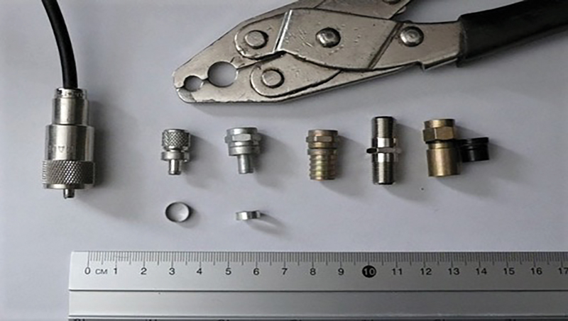
Figure 1. Left to right: PL-259 connector on 50 ohms impedance coax for comparison; C connector (1/8-inch crimp ring); F connector (1/8-inch crimp ring); hex crimp F connector; F-81 barrel splice; early compression style F connctor. The crimp tool at the top of the photo is for the 1/8-inch crimp rings.
Today’s F connector is covered by a number of standards such as ANSI/SCTE 01 2021, ANSI/SCTE 02 2021, ANSI/SCTE 123 2021, and ANSI/SCTE 124 2021.
Bonus question: What do the letters “BNC” from the popular BNC connector stand for? The answer’s at the end of the article.
It’s not what you think
CLI — One of the most misused signal leakage-related terms is cumulative leakage index, or CLI, which is not the same thing as signal leakage. CLI is a mathematical figure of merit that provides a snapshot of sorts of the magnitude of a cable system’s signal leakage. You must measure signal leakage in order to calculate CLI.
Digital technology
One very popular service that provides incremental revenue for cable operators is high-speed Internet access. This is done using cable modems, which are electronic devices that connect between the cable network and subscribers’ personal computers and other devices such as Wi-Fi access points. A cable modem converts RF signals from the cable network to digital data and vice versa. Cable modems comply with the Data-Over-Cable Service Interface Specifications (DOCSIS®) standard. The purpose of DOCSIS is to provide interoperability among various manufacturers’ cable modems and the headend/hub equipment used by cable operators. That headend/hub equipment is called a cable modem termination system (CMTS) or converged cable access platform (CCAP). The CMTS (or CCAP) converts digital data from the Internet to RF signals that can be carried on the cable network and vice versa.
cloud — A meme making the rounds on social media defines the cloud a bit tongue-in-cheek as “someone else’s computer.” When we say cloud computing, that often means the use of remote computer resources, located in a third-party server facility and accessed via the Internet. Sometimes the server(s) might be in or near a cable operator’s own facilities. What’s called the cloud is used for storing data, computer processing, and for emulating certain functionality in software that previously relied upon dedicated local hardware.
The evolving network architecture
extended spectrum DOCSIS — The DOCSIS 3.1 specification spells out technical parameters for equipment operation on HFC network frequencies from as low as 5 MHz to as high as 1002 MHz (also called 1 GHz), and extended operating ranges to 1218 MHz (aka 1.2 GHz) and 1794 MHz (aka 1.8 GHz). Operation on frequencies higher than 1.2 GHz has been called extended spectrum DOCSIS (ESD). The latest version of DOCSIS is the DOCSIS 4.0 specification, which defines metrics for operation up to at least 1.8 GHz. The phrase “extended spectrum DOCSIS” is being replaced by frequency division duplex (FDD), especially in the DOCSIS 4.0 specification.
FDX DOCSIS — What’s known as full duplex DOCSIS or “FDX” was originally an extension to the DOCSIS 3.1 specification (and is now part of the DOCSIS 4.0 specification) that supports transmission of certain downstream and upstream signals on the same frequencies at the same time, targeting data speeds of up to 10 gigabits per second (Gbps) in the downstream and 5 Gbps in the upstream! The magic of echo cancellation and other technologies allows signals traveling in different directions through the coaxial cable to simultaneously occupy the same frequencies.
distributed access architecture — As cable operators upgrade their networks and reduce the number of homes passed per fiber node to improve the effective data speeds per subscriber, it’s necessary to add more headend and/or hub equipment to support the larger number of nodes. Physical space in today’s headends and hub sites is limited; adding more equipment such as CMTSs and edge-QAM modulators (headend devices that generate and transmit downstream digital RF signals) can be difficult or impossible. As well, the additional equipment requires more electrical power and air conditioning. What to do?
One option is to migrate to a DAA, which involves moving some headend or hub electronics functionality to the outside plant. A subset of DAA now being deployed by cable operators is called remote physical layer, or remote PHY (R-PHY). In an R-PHY architecture a CMTS’s (CCAP’s) media access control (MAC) circuitry — the electronics that perform DOCSIS processing, among other things — remains in the headend or hub; the physical layer (PHY) circuitry is relocated to a shelf or an optical node. The PHY circuitry generates and transmits downstream RF signals (the equivalent of headend modulators and similar signal sources), and receives and processes upstream RF signals. In an R-PHY architecture, the PHY electronics are in a remote PHY device (RPD) module or circuit that’s installed in a shelf or node.
Part of the upgrade to an R-PHY architecture includes changing the optical fiber link electronics between the headend or hub and R-PHY nodes from analog to digital (typically 10 gigabit Ethernet), which helps to improve the cable network’s signal quality.
Another variation of DAA is remote MAC/PHY (R-MAC/PHY) in which the MAC and PHY functionality are relocated to the node or shelf.
Getting bits from here to there
quadrature amplitude modulation — “Modulation” is the general term used to describe how to transmit information — sound, pictures (video), or digital data — by varying one or more characteristics of an RF signal to represent that information. For instance, your favorite FM radio station uses frequency modulation, in which the frequency of the transmitted signal is varied to transmit voice and music. The cable industry uses QAM, a modulation method in which phase and amplitude variations of an RF signal represent digital data. Legacy digital video signals and DOCSIS data signals use what we now call single carrier quadrature amplitude modulation (SC-QAM). Each SC-QAM RF signal is 6 MHz wide (8 MHz in Europe and elsewhere).
OFDM — DOCSIS 3.1 technology uses orthogonal frequency division multiplexing (OFDM) in the downstream; OFDM’s upstream counterpart is called orthogonal frequency division multiple access (OFDMA). In the downstream, DOCSIS 3.1 OFDM channel widths vary from a minimum of 24 MHz to a maximum of 192 MHz (upstream OFDMA channel widths vary from 6.4 MHz to 95 MHz). An OFDM/A channel comprises up to several thousand very narrow bandwidth (25 kHz or 50 kHz) QAM signals, commonly called subcarriers. Each of those “miniature” QAM signals carries a small percentage of the total data payload.
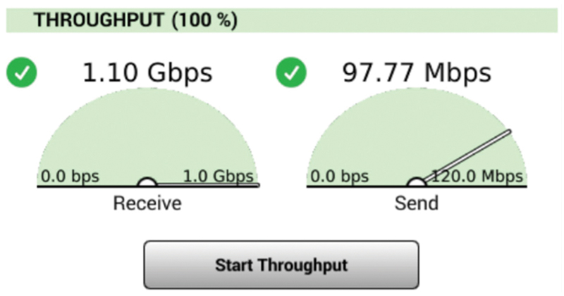
gigabit service — This is a class of high-speed data service in which the nominal data transmission rate is 1 Gbps, or 1 billion bits per second. Gigabit service can be asymmetrical — for instance, 1 Gbps in the downstream and 100 megabits per second (Mbps) in the upstream — or symmetrical (1 Gbps in both directions). Cable operators around the world have been deploying DOCSIS 3.1 cable modem technology to support gigabit-class data service over HFC networks. See Figure 2.
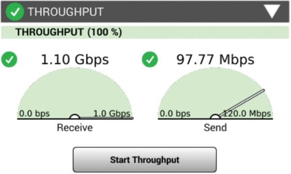
Figure 2. Example gigabit speed test for an asymmetrical service. Graphic courtesy of Viavi.
Technology marches on
Internet of Things (IoT) — From one perspective, IoT can be considered the point in time when more ‘things or objects’ were connected to the Internet than people. From another perspective, IoT is the interconnection and management of billions of wired and wireless sensors, embedded systems, appliances, and more. Making it all work, while maintaining privacy and security, and keeping power consumption to a minimum are among the challenges of IoT.
Wi-Fi 6 — This is the next generation of Wi-Fi technology, based upon the Institute of Electrical and Electronics Engineers (IEEE) 802.11ax standard (the sixth 802.11 standard, hence the “6” in Wi-Fi 6), that’s said to support maximum theoretical data speeds upwards of 10 Gbps. See Figure 3.
Figure 3. The Wi-Fi CERTIFIED 6™ program from the Wi-Fi Alliance® is for devices based on the IEEE 802.11ax standard.
wireless — Any service that uses radio waves to transmit/receive video, voice, and/or data in the over-the-air spectrum. Examples of wireless telecommunications technology include cellular (mobile) telephones, two-way radio, and Wi-Fi. Over-the-air broadcast TV and AM & FM radio are forms of wireless communications, too.
5G — According to Wikipedia, “5G is the fifth-generation cellular network technology.” You probably already have a smart phone or tablet that’s compatible with 4G (and earlier) cellular technology. Service providers are installing new towers in neighborhoods and elsewhere to support 5G, which provides their subscribers with much faster data speeds. Those towers have to be closer together (which means more of them) because of plans to operate on much higher frequencies than earlier generation technology. So, what does 5G have to do with cable? Plenty! For one thing, the cable industry is well-positioned to partner with telcos to provide “backhaul” interconnections between the new 5G towers and the telcos’ facilities. Those backhauls can be done over some of our fiber, as well as over our HFC networks using DOCSIS.
10G — Not to be confused with 5G, this term refers to the cable industry’s broadband technology platform of the future that will deliver at least 10 Gbps (that’s 10 billion bits per second!) to and from the subscriber premises. 10G supports better security and lower latency (less delay) and will take advantage of a variety of technologies such as DOCSIS 3.1 and 4.0, FDX DOCSIS, wireless, coherent optics, and more. See Figure 4.
![]()
Figure 4. The cable industry’s 10G initiative was introduced at the 2019 CES.
Hopefully this introduction helps to clarify some of the often confusing terminology used by the cable industry. Before I forget, here’s the answer to that earlier bonus question: BNC stands for “bayonet Neill Concelman.” The connector is named after its inventors, Paul Neill and Carl Concelman.
 Ron Hranac
Technical Editor,
Broadband Library
rhranac@aol.com
Ron Hranac, a 49 year veteran of the cable industry, has worked on the operator and vendor side during his career. A Fellow Member of SCTE and co-founder and Assistant Board Member of the organization’s Rocky Mountain Chapter, Ron was inducted into the Society’s Hall of Fame in 2010, is a co-recipient of the Chairman’s Award, an SCTE Member of the Year, and is a member of the Cable TV Pioneers Class of ’97. He received the Society’s Excellence in Standards award at Cable-Tec Expo 2016. He was recipient of the European Society for Broadband Professionals’ 2016 Tom Hall Award for Outstanding Services to Broadband Engineering, and was named winner of the 2017 David Hall Award for Best Presentation. He has published hundreds of articles and papers, and has been a speaker at numerous international, national, regional, and local conferences and seminars.