Proof-of-Performance Testing Requirements
By H. Mark Bowers
Part one FCC Proof-of-Performance [Analog review]
Since I often field questions regarding the measuring or interpretation of FCC Part 76 proof-of-performance (POP) rules and testing requirements, I thought it appropriate to review this subject in my next two articles. Given space limitations, we will review analog testing requirements here in Part One, and then in Part Two we’ll examine digital testing. And to keep it interesting, we’ll examine several unusual problems I discovered during recent testing trips.
Review of Present Rules
Whether you are conducting your first FCC proof-of-performance test or have been doing this for a long time (I conducted my first FCC POP test in 1974), make sure you periodically and carefully review the latest edition of FCC Part 76 rules. A detailed review of the latest rules in this article is not possible, so be sure to review them carefully. The following URL will take you to the most recent release: https://www.fcc.gov/general/cable-rules.
Testing is required once every six months in systems with more than 1,000 subscribers: first during the ‘coldest’ months (January-February) of the year and then again, during the ‘hottest’ months of the year (July-August). For systems less than 1,000 subscribers, compliance with all standards is still required; it is only the requirement for formal record keeping that is waived.
In the headend, all analog channels that deliver video programming to subscribers must be tested for visual and aural (intercarrier) frequencies, hum and low frequency interference (LFI), carrier-to-composite noise (CCN) or carrier-to-noise (C/N), in-channel response (ICR), and discrete intermodulation beats. Color tests (differential gain and phase, plus chrominance-to-luminance delay inequality (CLDI)) are required once every three years on all channels delivering video content. For analog carriers used for level setting or pilot carriers without video content, frequency measurements must still be made if the carrier lands within the aeronautical bands of 108 MHz to 137 MHz and 225 MHz to 400 MHz.
Regarding the number of channels to be tested in the field, the number of field test points required, plus other testing variables; review FCC Part 76.601 in its entirety. Pay close attention to subsection 76.601(1), as it addresses caveats such as the requirement for additional field test points, where there are “technically integrated portions of cable systems that are not mechanically continuous.” At field locations, the same tests are required that were conducted in the headend; only on a reduced number of channels, and composite intermodulation distortion is measured rather than discrete intermod.
When reviewing a complex set of rules, confusion in interpretation sometimes arise. If you find that you are not sure about what a rule or test requires, post a question to one of the several cable-related internet forums. And if you are still not sure, err on the side of caution (conduct the test if you are not sure). For example, I know of systems that use the formula to calculate the number of analog channels that must be tested at field test points and apply it to headend testing. I do not believe that position can be supported by any reasonable interpretation of Part 76 rules. At the headend, the only logical interpretation is that all channels or carriers should be tested; as this establishes a baseline for all field measurements, and ensures all critical measurements are conducted at least once on each channel or carrier in the system.
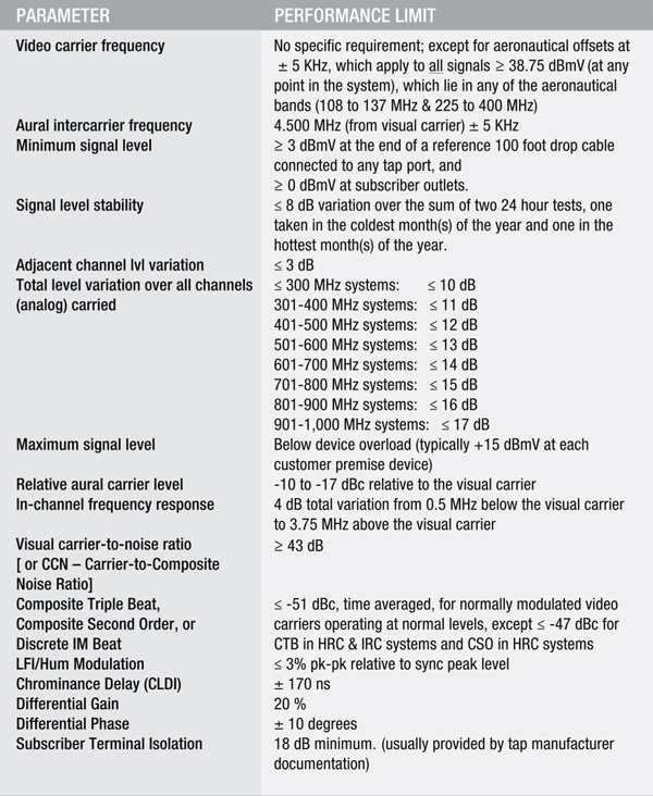
Specific analog tests and performance limits are summarized in the following chart:
Treasure Hunt
As a general rule, I enjoy proof-of-performance testing immensely, because in many ways I feel as if I’m on a treasure hunt when I head out to conduct tests. I often discover at least one unusual problem while testing in the headend or at field locations, and that’s what keeps it interesting and challenging for me.
The four screen captures accompanying this article illustrate two unusual problems found during recent testing trips. The first problem was found during headend testing, while the second was discovered during field testing.
Headend Problem: Screen Capture One depicts the combined output of eight RF ports from a popular ‘IP to analog’ modulator system. The spectrum captured is from approximately 54 MHz to 504 MHz. These ‘IP to analog’ systems are typically fed via one or several GigE inputs and can create an entire analog channel lineup.
Advantages to this system are many, including that it’s all contained in a single unit that is typically one rack space high and that vertical interval test signals (VITS) such as multiburst, FCC composite, etc., can be inserted in the vertical interval of each channel, making it much easier to perform ICR and color testing.
It is unusual to encounter problems with these units because most are relatively new; however, during a recent headend proof the system tech mentioned that some of his analog channels had faint white sparkles in the background. And sure enough, some (but not all) of the channels had what appeared to be faint impulse noise. In Screen Capture One the black trace is ‘real time’ and the ‘red trace’ is ‘peak-hold.’ The red trace demonstrates that impulse-type noise was present and confined to two regions; approx. 100 MHz to 170 MHz and approx. 300 MHz to 435 MHz. The lower noise region centered around a single carrier (Ch. 17), while the upper region centered around a group of three carriers (Ch. 51 through 53). We then used the control software to ‘mute’ the two offending output ports to confirm our spectrum analysis; that two of the eight ports were generating this impulse-type noise. Screen Capture Two shows the same 8-way combiner with the defective channel groups muted and impulse noise gone.
Field Problem: Another FCC POP outing involved field testing in a cluster of four systems. The first system was fed via a separate laser, the closest system geographically to the headend. The remaining (three) more distant systems were fed via a laser transmitter + erbium doped fiber amplifier (EDFA) pair. Screen Capture Three depicts Ch. 50 through 54 in the system fed from the separate laser. The black trace is ‘real time’ and the green trace is ‘minimum-hold.’ With a trace in ‘minimum hold,’ only signals that are on all the time remain on the screen; all other spectrum eventually ‘zeros out,’ leaving the trace at the ‘cumulative noise floor of the system plus the spectrum analyzer.’ In Screen Capture Three the ‘minimum-hold’ trace appears as expected, with only the visual and aural carriers remaining, since other carriers (and sidebands) are ‘off’ during NTSC-M analog transmission at periodic times.
In Screen Capture Four, note the addition of approximately 20 beats of varying amplitude in the green ‘minimum-hold’ trace that were not present in the previous system.
This system (plus two others) was fed from the laser transmitter + EDFA pair. Hundreds of low-level beats were present throughout the entire spectrum, and were not related to composite triple beat (CTB) or composite second order (CSO). We can confirm this because CTB distortions always land under the visual carrier so we would not be able to view them using the ‘minimum-hold’ technique unless there was an open channel slot (where the CTB spur could be seen), and CSO beats land at each visual carrier frequency ± 0.75 MHz and ± 1.25 MHz. The beats shown on this ‘minimum hold’ trace do not fit that pattern either.
Although not readily apparent, the beats in Screen Capture Four meet the following relationship: [luminance carrier ± ~3.5 MHz] and [aural carrier ± ~3.5 MHz]. The two vertical red markers are 3.5 MHz apart, thus illustrating the relationship between the Ch. 53 luminance carrier and the higher amplitude beat under the Ch. 53 color subcarrier [luminance carrier + 3.5 MHz]. All beats were eliminated when the laser transmitter (launch laser) was replaced at the master headend.
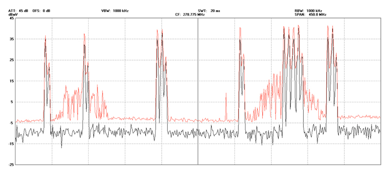
Screen Capture One: Output of ‘IP to analog modulator system’ 8-port combiner
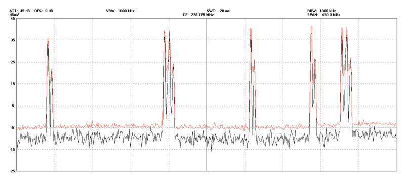
Screen Capture Two

Screen Capture Three
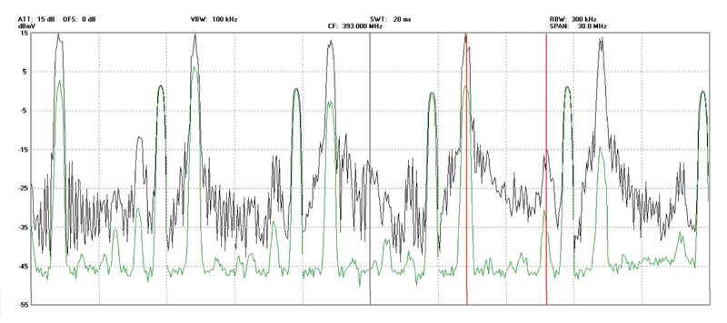
Screen Capture Four
Part One Summary
In summary:
- Review a recent edition of FCC Part 76 rules if you have not already done so this year, and make sure you have a good grasp of what is required in the headend and at field test points.
- Sample FCC proof-of-performance reports can often assist in answering questions. You can obtain a sample Cablesoft Engineering, Inc. FCC POP Report (data is from an actual system proof) at the download page of our web site. One note: My reports contain extra verbiage that is not officially required by FCC rules; however, in my experience it greatly assists local personnel in understanding the overall results of their FCC tests.
In Part Two we will review requirements for digital signal testing, which is mandatory if your system has an activated bandwidth of 750 MHz or greater.
H Mark Bowers,
Cablesoft Engineering, Inc.
Mark is VP of Engineering at Cablesoft Engineering, Inc. He has been involved in telephony since 1968 and the cable industry since 1973. His last industry position was VP of Corporate Engineering for Warner Cable Communications in Dublin, OH. Mark’s education includes the U.S. Naval Nuclear Engineering School, and BS and MS Degrees in Management of Technology. Mark is a member of the SCTE, the IEEE, and is a Senior Member and licensed Master Telecommunications Engineer with iNARTE.