A Review of FCC Proof-of-Performance Testing Requirements
By H. Mark Bowers
Part one FCC Proof-of-Performance [Digital Review]
In my last column we examined analog testing requirements under present FCC Part 76 rules. For a review of those requirements, see the Testing In Progress column of the Winter Edition 2016 archived on broadbandlibrary.com. Part Two now examines FCC requirements for digital testing, and by digital I mean the testing of quadrature amplitude modulation (QAM) carriers.
Review of Present Rules
As noted in Part One, FCC Proof-of-Performance testing is required once every six months in systems with over 1,000 subscribers: first during January or February, the ‘coldest’ months of the year; and then again during July or August, the ‘hottest’ months of the year. For systems under 1,000 subscribers, compliance with all standards is still required; it is only the requirement for formal record keeping that is waived.
As a preface to QAM testing, a review of the ANSI/SCTE 40 2003 Digital Cable Network Interface Standard is highly recommended. A copy of ANSI/SCTE 40 2003 is available from SCTE upon request. When reviewing testing on QAM carriers, the requirements can ‘seem’ a bit muddled at first; but a careful review of present rules and standards provides answers to most questions. FCC Part 76.640 addresses digital standards including the testing of QAM carriers. The following section is only the opening portion of FCC Part 76.640 rules; therefore as you have time you should review it in its entirety.
- 76.640 Support for unidirectional digital cable products on digital cable systems
- The requirements of this section shall apply to digital cable systems. For purposes of this section, digital cable systems shall be defined as a cable system with one or more channels utilizing QAM modulation for transporting programs and services from its headend to receiving devices. Cable systems that only pass through 8-VSB broadcast signals shall not be considered digital cable systems.
- No later than July 1, 2004, cable operators shall support unidirectional digital cable products, as defined in §15.123 of this chapter, through the provisioning of Point of Deployment modules (PODs) and services, as follows:
- Digital cable systems with an activated channel capacity of 750 MHz or greater shall comply with the following technical standards and requirements:
- SCTE 40 2003 (formerly DVS 313): “Digital Cable Network Interface Standard” (incorporated by reference, see §76.602), provided however that with respect to Table B.11, the Phase Noise requirement shall be −86 dB/Hz, and also provided that the “transit delay for most distant customer” requirement in Table B.3 is not mandatory.
Through a careful read of this opening section of 76.640 we can conclude the following:
- 8-VSB measurements do not fall under these rules, only QAM modulated carriers.
- Part 76.640 (b)(1) states that QAM testing is mandatory if the plant has an activated bandwidth of 750 MHz or greater. There still seems to be some confusion among cable operators and even some testing companies as to whether QAM testing is mandatory; however, the rules are quite clear. It is mandatory.
- Note that part 76.640 (b)(2) references a SCTE 40 2003 standard, however a search of the SCTE web site (scte.org) finds no such document. The current version on SCTE’s web site is ANSI/SCTE 40 2016. Copies of earlier versions, including ANSI/SCTE 40 2003 and ANSI/SCTE 40 2004, are available from SCTE upon request. The technical parameters in Table B of ANSI/SCTE 40 2003 referenced in FCC Part 76.640 are the same in the 2003 and 2004 versions.
- The phase noise standard is slightly relaxed as compared to the ANSI/ SCTE 40 2003 standard, and the ‘transit delay for the most distant customer’ measurement is waived at present.
- The most recent edition of the ANSI/SCTE 40 standard is 2016, which relaxes Group Delay to ≤ 370 nanoseconds across the 6 MHz channel, and Max Amplitude Variation to ≤ 6 dB peak-valley across the 6 MHz channel.
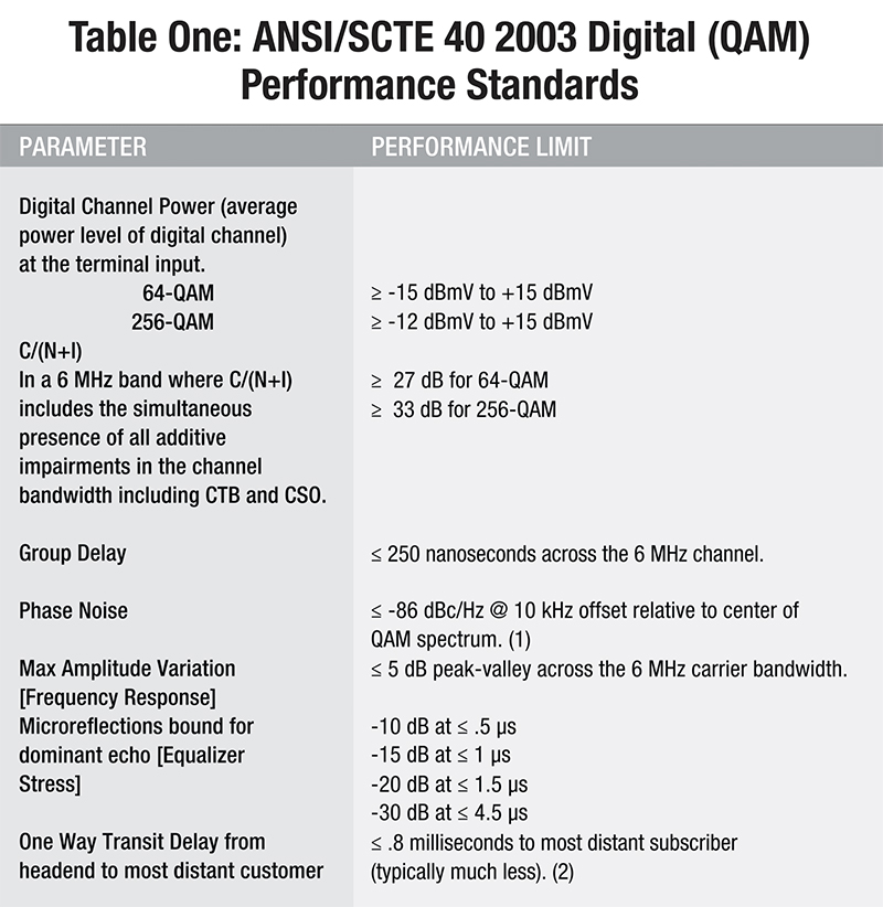
Notes 1. Although ANSI/SCTE 40 2003 specifications for phase noise are -88 dBc/Hz, FCC Part 76.640 rules presently ‘relax’ this spec. to -86 dBc/Hz. Phase Noise is difficult to measure accurately except with laboratory grade test equipment. At present, there are no field QAM analyzers that I am aware of that can perform this measurement to full SCTE 40 2003 specifications. 2. Transit Delay measurements are optional per FCC 76.640 rules.
Common Issues
The following are some common problems and/or questions I encounter during testing.
- Old HITS ‘Classic’ headends, where C6U and C8U upconverters are still in use, can exhibit unusual problems, either because of age related failure or because they are not configured properly. The setting of proper RF input and output levels is a common issue. And early release SEM v8 units have reached an age where failures are not uncommon, such as poor output port frequency response. High hum levels on QAM carriers due to aging upconverters are another common problem found.
- QAM average power levels should be carefully maintained in the headend. I normally check and adjust output levels to –6 dBc ±1 dB relative to the closest analog carriers. If RF average power levels vary too much at the headend, you can only expect them to be worse at field test points. Narrowcast DOCSIS® carriers, if not maintained properly, will often show great variation as compared to video QAM carriers. And make sure your QAM analyzer or meter incorporates a routine to accurately measure ‘average power levels’!
- I’m often asked how many QAM carriers need to be tested in the headend and at field test point locations, since FCC rules and SCTE standards do not stipulate these numbers. My recommendation reflects a common sense approach that ‘mirrors’ what is required on the analog side.
- Headend: All QAM carriers are tested to full ANSI/SCTE 40 2003 specifications.
- Field TPs: Selected video QAM carriers are tested plus all DOCSIS QAM carriers. My methodology is to ‘rotate’ through all video QAM carriers, typically testing 1/3 of the video QAM carriers at each test point, such that after three field test points I’ve tested all video QAM carriers at least once. And I normally test all DOCSIS QAM carriers at all field test points, since these are usually narrowcast with different DOCSIS QAM carriers present at each field test point. Since high-speed Internet is an important service offering for the cable operator, I believe it is important to test all DOCSIS QAM carriers at every field test point.
- When choosing a QAM analyzer, consider one that allows for fully automated QAM testing, since this testing can be quite time consuming as the number of analog carriers decreases and the number of QAM carriers increases in most systems. My automated QAM testing setup takes approx. 70 seconds to test each QAM carrier (approximately 25 tests per carrier). If, for example, there are 60 total QAM carriers including DOCSIS, that’s 20 carriers per field test point at 70 seconds/carrier, for a total testing time on the QAM side alone of 23 to 24 minutes. And ideally, the automated testing routine should provide for exporting your testing results in a format that allows for importing and grading in an Excel spreadsheet.
Treasure Hunt
It’s often QAM carrier testing that discloses subtle system problems that analog testing may not reveal. This is particularly true during field testing, and it is one of the reasons I began to include QAM testing as part of my FCC Proof-of-Performance package long before it was required by FCC rules.
The screen captures below illustrate simple problems found during recent testing trips. Regarding trace colors: a red trace indicates ‘peak-hold’, a black trace is ‘real-time,’ and a blue trace represents an ‘average of 25 traces.’
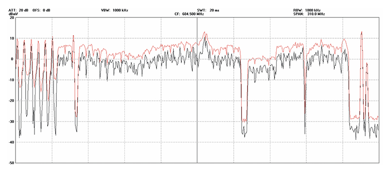
Screen Capture One illustrates the effect of the careless setting of QAM average power levels at the headend. Although some of the RF level variation through the QAM carrier region is a result of plant frequency response issues, most of the QAM average power level variation occurs at the headend, with a similar response seen at all field test points. QAM average power levels need to be carefully maintained for several reasons, and Screen Capture One illustrates the result of not following this regimen.
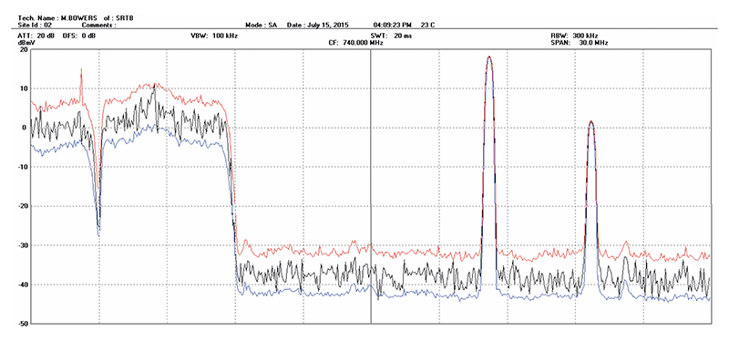
Screen Capture Two illustrates poor QAM (system) frequency response due to ‘standing waves’ coupled with the presence of low-level intermod products in the high frequency spectrum at a field test point. MER, equalizer stress, frequency response, along with other parameters were affected by this frequency response issue, which traced to deteriorating sheath in a buried .750” coaxial express cable run.
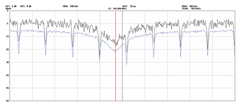
Screen Capture Three illustrates a common problem encountered in the field. A ‘frequency response suckout’ (impedance mismatch) in the network creates a sloped response across four QAM carriers, with the worst response centered at 543 MHz (Channel 85). This response problem adversely affected various QAM testing parameters in QAM carriers 84 through 87; however only QAM carrier 85 failed frequency response and equalizer stress measurements.
Part Two Summary
- Despite what you may have heard or read, if your activated plant bandwidth is 750 MHz or greater and if you are utilizing QAM carriers in your plant, testing is required as outlined in this article.
- Review the most recent edition of FCC Part 76.640 rules if you have not done so.
- Obtain a copy of ANSI/SCTE 40 2003 from SCTE.
- Make sure your test equipment is properly calibrated. In general, test equipment used during FCC Proof-of-Performance testing should be calibrated every 12 months. Calibration services can be expensive, but it is a crucial precaution to ensure accurate testing results.
- If your QAM analyzer can measure phase noise, even though not fully adhering to the standard specified in ANSI/SCTE 40 2003, measure and record this parameter, as it offers a baseline for ‘normalized’ performance across all QAM carriers.
“In my next column we will examine scalar testing (frequency response, isolation, and return loss), how they are measured, and why it’s important.”
 H. Mark Bowers,
Cablesoft Engineering, Inc.
Mark is VP of Engineering at Cablesoft Engineering, Inc. He has been involved in telephony since 1968 and the cable industry since 1973. His last industry position was VP of Corporate Engineering for Warner Cable Communications in Dublin, OH. Mark’s education includes the U.S. Naval Nuclear Engineering School, and BS and MS Degrees in Management of Technology. Mark is a member of the SCTE, the IEEE, and is a Senior Member and licensed Master Telecommunications Engineer with iNARTE.