Resistance, Reactance and Impedance
By H. Mark Bowers
One of my Christmas gifts last December was the book “The Forgotten Genius of Oliver Heaviside — A Maverick of Electrical Science.” Oliver Heaviside was English (1850 to 1925) and spent most of his life developing his theories alone — a true reclusive genius. I had never heard of him, but it would appear he deserves far greater recognition because he developed many of the theoretical concepts we now take for granted. In one of his early published papers Heaviside reformulated Maxwell’s theory of electromagnetism (originally 12 equations that baffled most scientists of his time) into the four Maxwell’s Equations now familiar to all electrical engineers. In that same paper published in 1885, Heaviside developed a formula for energy flow through an electromagnetic field that demonstrated electrical energy doesn’t flow in a wire but rather in the space alongside the wire. Most of Heaviside’s work has been collected into five volumes that together total more than 2,500 pages!
The intent in this and some future articles is to review a few of these basics that were taught to many of us early on but are now seldom used. Here I begin with resistance, reactance, and impedance. Also, let me state the obvious: this column will only permit a cursory examination of these concepts because space does not allow for a full analysis.
Resistance
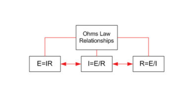
Resistance as defined by Ohm’s Law is “the circuit characteristic that limits current flow.” Resistance may arise from a discrete component such as a resistor, or can represent the cumulative opposition to current of wire(s), cable(s), or transmission line(s) including coaxial cable. Resistance, by definition, provides a value in ohms at zero frequency (direct current or DC).
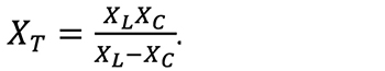
See Figure 1 for Ohm’s Law relationships between current, voltage, resistance and power.
When dealing with frequencies greater than zero (alternating current or AC), we find that resistance alone is insufficient to properly quantify the total opposition to current flow in a circuit. This leads us to reactance.
Reactance
Reactance (X) is defined as “that part of the overall opposition to current flow in an AC circuit due to capacitance, inductance, or both, and is expressed in ohms.” Reactance has both magnitude and phase values, and further separates into inductive and capacitive components.
Inductive reactance
Inductive reactance (XL) is that portion of total circuit reactance contributed by coils, chokes, and transformer windings. Any device in which wire is wound circularly is an inductor. Inductors tend to oppose any change in current over time. This is because current flowing through an inductor generates a magnetic field. In a direct current circuit, the intensity and direction of the magnetic field remain constant. As a result, current flows easily through the inductor since it simply appears as a length of wire. Magnetic fields, by nature, resist change and oppose any change in current. In an AC circuit the magnetic field must change constantly as the magnitude and direction of current flow changes. Thus, an inductor passes lower frequencies more easily than higher frequencies. This opposition to a change in current flow is inductive reactance and is defined by the formula:
where XL is inductive reactance in ohms, π is 3.14159(…), F is frequency in hertz, and L is inductance in henrys.
Capacitive reactance
Capacitive reactance (XC) is that portion of total circuit reactance caused by capacitance. Capacitance results when two conducting surfaces are parallel to each other and separated by a small distance with a non-conducting substance (dielectric). An example is the discrete circuit component called a capacitor. Capacitors are voltage limiting devices in that they tend to oppose voltage change over time.
When a DC voltage is applied to a capacitor, the capacitor draws a current and charges up to the value of the applied voltage. In an AC circuit, the lower the frequency of the applied voltage, the more time the capacitor has to charge before the voltage reverses polarity and the capacitor begins to discharge. The capacitor therefore spends more time fully charged and passing less current, resulting in less current flow (higher reactance) at low frequencies. As frequency increases, the capacitor changes from charging to discharging faster, allowing more current to flow (lower reactance). Capacitive reactance therefore decreases as frequency increases. The actual value of XC is inversely proportional to the value of capacitance and the frequency as shown in the formula:
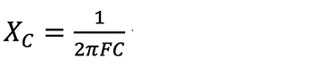
where XC is capacitive reactance in ohms, π is 3.14159(…), F is frequency in hertz, and C is capacitance in farads.
Impedance
Impedance (Z) is the total opposition to current flow in an AC circuit that contains resistance and reactance, and here’s where it gets interesting. If a circuit, for example, were purely inductive (no resistance), XL would represent the total opposition to current flow. In this example Z and XL are identical and are represented by a value of some magnitude with a -90° phase angle (ɵ or theta). If the circuit were purely capacitive, the same would be true except ɵ shifts to +90°. The phase of the current is always stated relative to the voltage (leading or lagging). AC networks typically contain elements of resistance, inductance and capacitance, and therefore the impedance must be a complex value with magnitude and phase (a vector). The magnitude portion of Z in a circuit can be calculated as shown in the following formulas.
In a series circuit impedance is calculated by
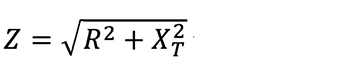
where XT = XL – XC (XT is combined circuit reactance).
In a parallel circuit impedance is calculated by
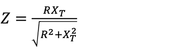
where
Now examine the circuit in Figure 2 that contains a combination of resistance and capacitance (no inductance to keep this simple). Note that the resistive and reactive currents do not numerically total as we might expect; 1.0 ampere resistive current plus 1.0 ampere reactive current equals 1.414 amperes total current. This is confusing until we examine Figure 3.
Figure 3 depicts a current triangle as a visual aid to illustrate magnitude and phase. It shows the relationship between the resistive, reactive, and total currents flowing in our sample circuit. If we plot a resistive current of 1 ampere on the x axis (0° theta) and 1 ampere reactive current on the y axis (+90° theta), total current is represented by the length of the hypotenuse at 1.414 amperes with a leading 45°phase angle.
It’s now obvious that impedance and power in this circuit must also be complex (vectors) and indeed they are. Using the formula for Z (shown earlier) for a parallel circuit yields 70.7 ohms for this RC circuit but doesn’t provide the phase angle. An impedance triangle can be constructed similar to Figure 3 (not shown). For Z, however, the process is not straightforward, as we first must calculate an equivalent series circuit and then build the triangle. When we do, the result yields a complex Z of 70.7 ohms with a +45° theta.
In a power triangle (also not shown), the horizontal axis represents true power (resistive, 100 watts), the vertical axis reactive power (100 vars), and the hypotenuse equals the apparent power of 141.4 volt-amperes. Further, the cosine of the 45° phase angle is 0.707, which equals the power factor (pf) in this circuit. Power factor is an important concept in electric utility power distribution networks and in my opinion an easier way to conceptualize and calculate reactive currents and power.
For an expanded article including the impedance and power triangles, see the Downloads Page of my website at www.cablesoftengineering.com. We’ll continue this review in my next column as we move on to parameters specific to coaxial cable.
—
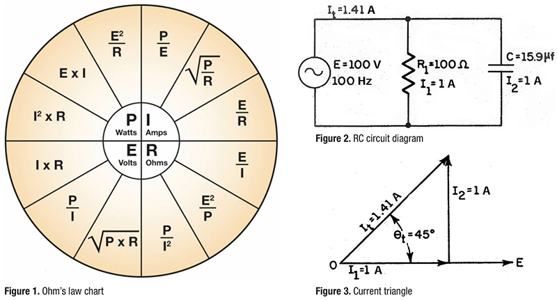
Figure 1. Ohm’s law chart
Figure 2. RC circuit diagram
Figure 3. Current triangle
 H. Mark Bowers,
Cablesoft Engineering, Inc.
Mark is VP of Engineering at Cablesoft Engineering, Inc. He has been involved in telephony since 1968 and the cable industry since 1973. His last industry position was VP of Corporate Engineering for Warner Cable Communications in Dublin, OH. Mark’s education includes the U.S. Naval Nuclear Engineering School, and BS and MS Degrees in Management of Technology. Mark is a member of SCTE•ISBE, IEEE, and is a Senior Member and licensed Master Telecommunications Engineer with iNARTE.