FCC Proof-of-Performance Rules Revisited
By H. Mark Bowers
Revisions to FCC Part 76 Rules were released in April of this year. Significant changes were included in this release, including the rewording of some test procedures and standards, QAM carrier limits for aeronautical frequency notification (AFN) and signal leakage, the simplification of some requirements, and a general simplification of wording in many areas. Ron Hranac and I co-authored an article in the Spring Edition of Broadband Library in which we reviewed the major changes in the April release. However, note that we wrote that article in January 2018, four months before the actual release of the new Rules pending at that time. There were several last minute changes in the final release that vary from our review, so I strongly recommend you take time to read FCC Part 76 (Subpart K at a minimum) as soon as possible.
The latest FCC Part 76 Rules are found at:
The Spring Broadband Library overview by Ron and me is found at:
As I prepared to write this article, I spent several days carefully reviewing Subpart K in its entirety and was surprised at the number of changes noted. Some, as already mentioned, are a simplified wording of some sections, with the overall intent of the Rules remaining the same. In other sections definite changes are evident. Now let’s review changes in FCC Part 76 Subpart K that are associated with FCC POP testing only; those sections include §76.601, §76.602, §76.605, §76.609, and §76.612. FCC §76.640 is loosely tied, but only as it relates to mandatory compliance with SCTE 40 2016 if your activated channel capacity is 750 MHz or greater. I will not review areas that address new signal leakage standards, CLI methodology, AFN requirements, or other areas as there simply isn’t room in this article to do so. My decision to focus on FCC Proof-of-Performance comes from a distinct impression, and I hope I’m wrong, that some systems and technicians now believe the entire FCC POP test is optional. If you are under that impression, it’s incorrect.
Finally, if I don’t address something in the following review, it’s because there were no changes in the latest Rules released in April that I could determine.
FCC Part 76 Subpart K Changes Review 
FCC Part §76.601, Performance Tests.
- §76.601(b)(2) clarifies what seemed to be an area of confusion in the past. The standards set forth in §76.605(b)(3), (4), and (5) [Minimum RF Levels, 24 Hour Level Variation, and Visual-to-Aural Level Variation tests] are required on all NTSC channels.
- Unless otherwise noted, proof-of-performance tests for all other standards in §76.605(b) shall be made on a minimum of five (5) channels for systems operating with a total activated channel capacity of less than 550 MHz, and ten (10) channels for systems operating with a total activated channel capacity of 550 MHz or greater. The channels selected for testing must be representative of all the channels within the cable television system. While this allows for the testing of only five or 10 channels in the headend and at field test points for the remaining standards, good engineering practice suggests that you test all of your NTSC channels for ICR (in-channel response), C/N (carrier-to-noise), coherent disturbances (discrete and composite intermodulation), and LFI (low frequency disturbances) in the headend; especially if your test equipment allows for automated testing. The five/ten channel rule is something I would recommend you apply to field test points only, but that’s just my recommendation, as it would appear to apply to the headend as well.
FCC Part §76.602, Incorporation by reference.
You should review this Rule section and note how many other technical standards are incorporated by reference into FCC Part 76 Rules. By my count, there are 10 reference documents referenced in this section. Compliance with the standards contained within these reference documents is also required, with ANSI/SCTE 40 2016 QAM carrier standards as a good example.
FCC Part §76.605, Technical Standards.
- This section begins by stating in the first paragraph “(a)Each cable system that uses QAM modulation to transport video programming shall adhere to ANSI/SCTE 40 2016 (incorporated by reference, see §76.602).” It does not require that all QAM carriers be tested periodically nor do they have to be included in your semi-annual FCC POP testing. I would again suggest that good engineering practice dictates you test all QAM carriers periodically to be sure they meet the requirements in ANSI/SCTE 40 2016. And if your test equipment provides for automated QAM testing, why not measure and document QAM testing results during your FCC POP testing?
- The requirements for NTSC testing were already addressed in my comments on FCC Part §76.601. My earlier review, however, does not address the requirements for the so-called color tests. FCC Part §76.601(2)(ii) states “The operator of each cable television system that operates NTSC or similar channels shall conduct triennial proof-of-performance tests of its system to determine the extent to which the system complies with the technical standards set forth in §76.605(b)(11).” §76.605(b)(11) states that color testing should be conducted once every three years “as measured at the output of the modulating or processing equipment (generally the headend) of the system.” The Rules do not stipulate whether these tests (CLDI, differential gain and differential phase) are to be conducted on all processors and modulators or just the five or 10 channel sampling; however, since the measurements are required only once every three years and since the tests are required at the output of the processing equipment, I would urge caution in this area, and recommend these tests be conducted on all NTSC channels at the point at which they are created.
- Finally, Part §76.605(c), in Table 1 to Paragraph (c) lists signal leakage limits for QAM carriers and NTSC carriers in two frequency bands. Be sure to review this table as new limits are now in place for QAM carrier leakage.
FCC Part §76.609, Measurements.
This Rule section that pertains to ‘how’ the various tests are conducted has not substantially changed. I would point out several sections that we all tend to ‘skip over’ at times.
- §76.609(g) addresses the subject of terminal isolation. It states “(g) The terminal isolation between any two terminals in the cable television system may be measured by applying a signal of known amplitude to one terminal and measuring the amplitude of that signal at the other terminal. The frequency of the signal should be close to the mid-frequency of the channel being tested. Measurements of terminal isolation are not required when either:
- The manufacturer’s specifications for subscriber tap isolation based on a representative sample of no less than 500 subscribers taps or
- Laboratory tests performed by or for the operator of a cable television system on a representative sample of no less than 50 subscriber taps, indicates that the terminal isolation standard of §76.605(a)(9) is met.
To demonstrate compliance with §76.605(a)(9), the operator of a cable television system shall attach either such manufacturer’s specifications or laboratory measurements as an exhibit to each proof-of-performance record.” [emphasis added by author]
- For systems still utilizing passive traps (positive or negative) to control access to certain channels, §76.609(i) states “For systems using cable traps and filters to control the delivery of specific channels to the subscriber terminal, measurements made to determine compliance with §76.605(a) (5) and (6) may be performed at the location immediately prior to the trap or filter for the specific channel. The effects of these traps or filters, as certified by the system engineer or the equipment manufacturer, must be attached to each proof-of-performance record.” In other words, if your NTSC visual-to-aural separation and ICR measurements do not include trap response (if your system uses them), then your report must include a document (local testing or from the manufacturer) specifying how those traps may impact the response of these two measurements.
FCC Part §76.612, Cable television frequency separation standards.
This section defines the requirements to properly offset NTSC carriers in certain frequency bands by either +12.5 kHz or +25 kHz and remains basically as it was in previous Rules. Note that §76.612 states there is a signal power level limit that triggers this offset requirement. 76.612(a) states offsets must occur if NTSC carrier power levels are “an average power level equal to or greater than 10−4 watts in a 25 kHz bandwidth in any 160 microsecond period.” This RF NTSC power level limit that equates to +38.75 dBmV applies to both offsets, +12.5 or +25 kHz, depending on the frequency band, and applies to any point in the plant. In past Part 76 Rules, the headend has been thought by some to be exempt from this power level limit; however I see nothing in my read of Part 76 Subpart K that would lead me to that conclusion. Therefore every cable system in operation likely meets this requirement (exceeds these power levels at some point) if the headend/hub is included. Please review Part 76.612(a), (b) and their subparts for further detail.
FCC Part §76.640, Support for unidirectional digital cable products on digital cable systems.
I mention this section only because ‘if’ the activated channel capacity of your system is less than 750 MHz you are exempt from meeting some requirements including ANSI/SCTE 40 2016, along with others including ANSI/SCTE 65 2002 and ANSI/SCTE 54 2003.
Final Observations and Recommendations
My final observation and recommendation regarding FCC Part 76 Subpart K Rule changes is that you really need to review these new rules yourself. My printout of Subpart K using a font size of 11 was 18 pages in length. Yes, it takes some time to review, with a fair amount of page flipping as one section may refer you to another. But it is time well spent. Semi-annual FCC POP testing on your NTSC carriers remains mandatory, while QAM testing to ANSI/SCTE 40 2016 specifications is optional but highly recommended, since you must ultimately comply with those standards unless your activated channel capacity is less than 750 MHz.
My review of FCC Part 76 Subpart K also led to a review of NCTA Recommended Practices, 2nd Edition, issued in 1989. Although the testing procedures described are all still valid, it’s interesting to note how most of these procedures have been greatly simplified over the years through the introduction of today’s specialized test meters and spectrum/QAM analyzers. Few testing labs or systems still have separate tracking generators, waveform monitors, and other equipment listed in these recommend practices. I’m not stating that the procedures described are invalid; but rather pointing out how much has changed on the test equipment side since then. “SCTE Measurement Recommended Practices for Cable Systems, Fourth Edition” includes updates to earlier versions of “NCTA Recommended Practices,” including most of the digital measurements applicable to SCTE 40 technical parameters. And that thought pattern led me to wonder how many of the tests described in FCC Subpart K (FCC Part §76.605, Technical Standards) could be accurately performed with a modern general purpose RTA-VSA (real-time analyzer, vector signal analyzer)?
So, as I close out this column I thought it might be informative, space permitting, to see which standards measurements could be made with a low-cost general purpose RTA-VSA. A modern real-time spectrum analyzer is completely digital in terms of signal processing. This allows for various measurements, options and displays that can be customized by the operator to a great degree.
A C/N measurement on Channel 15 taken with a general purpose RTA in an operational system is shown in Diagram One. NCTA Recommended Practices, 2nd Edition, specifies C/N should be measured at a 25 kHz IF bandwidth rather than the 10 kHz I used, which then must be normalized to a 4 MHz video bandwidth for NTSC-M modulation. Adjusting from 10 kHz to 4 MHz yields a correction factor of 26.02 dB. The delta between visual carrier RF level to the video/RF noise floor in Diagram One is 74.37 dB (see marker delta value in upper right corner of the waveform). Now subtract the 26.02 dB IF BW correction factor yielding a C/N value of 48.35 dB. If I had measured with a 25 kHz IF bandwidth, the correction factor would be 22.04 dB. This measured C/N value is ± .5 dB of that measured with an analyzer customized for FCC POP measurements.
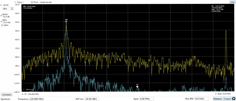
Diagram One — C/N Measurement. The yellow trace is ‘real time,’ the blue trace is ‘minimum hold.’
Also, note that virtually all general purpose spectrum analyzers have an input impedance of 50 ohms. To obtain RF levels in dBmV on the waveform add a correction factor of 55 dB. For example, the MR (reference) marker shows the visual carrier level at -40.85 dBm. The level in dBmV is -40.85 dBm +55 dB correction equals +14.15 dBmV. The correction factor comes from (a) adding 48.75 dB to convert from dBm to dBmV, and (b) 5.7 to 6.0 dB of loss from the 50 ohm to 75 ohm matching pad (minimum loss pad).
I measured most FCC POP measurements with this general purpose RTA if it was possible to do so; however, space does not permit me to show more than this single waveform. To view all of my measurements along with additional comments on the pro’s and cons of a RTA, use the following link to download all results: http://www.cablesoftengineering.com/downloads.html
The download file is towards the bottom of that page and is titled ‘FCC POP Measurements with a RTA.’ If you don’t have time to download and review all tests, the bottom line summary is yes, you can perform many if not most of these standards tests with a RTA; however measurement speed is a negative factor and use of a spectrum analyzer customized for FCC measurements is highly desirable if you have one.
 H. Mark Bowers,
Cablesoft Engineering, Inc.
Mark is VP of Engineering at Cablesoft Engineering, Inc. He has been involved in telephony since 1968 and the cable industry since 1973. His last industry position was VP of Corporate Engineering for Warner Cable Communications in Dublin, OH. Mark’s education includes the U.S. Naval Nuclear Engineering School, and BS and MS Degrees in Management of Technology. Mark is a member of the SCTE, the IEEE, and is a Senior Member and licensed Master Telecommunications Engineer with iNARTE.
Credit: Charts provided by author