Longitudinal Sheath Current Revisited
By H. Mark Bowers
Introduction: I wrote my first industry article on this subject in 1989 after conducting meetings and research with electric utilities, plus taking measurements in operational cable systems. Recent questions from several industry colleagues convinced me it was time to readdress this subject. The purpose of this summary is to provide a foundation for better understanding of these issues along with possible remedial actions. Space restrictions in this Broadband Library issue do not permit a full examination of these issues. For a more in-depth analysis use the following URL: http://www.cablesoftengineering.com/downloads.html to download the complete article.
Summary: Longitudinal sheath current (LSC) describes the condition in an outside cable television plant when AC currents are flowing on the coaxial cable sheath that are created by load imbalance currents external to the self-regulating cable plant power supply. Any load imbalance in the electric utility primary and/or secondary system(s) creates current flow in their neutral conductor. Our outside plant carries a portion of this current because of our shared (bonded) path with their grounded-neutral system. Since the cable plant is bonded to this system via the utility pole ground vertical, our sheath carries a portion of this current to the extent of the ratio of the overall impedance of our conductive plant to theirs. This carriage of neutral current on the coaxial sheath induces longitudinal voltages in the coaxial cable center conductor.
Creation and Impact of Longitudinal Sheath Currents
Cable systems are required to bond to the electric utility grounded-neutral conductor system according to National Electrical Safety Code (NESC), along with local codes when applicable, which outline required safety and construction practices for the outside plant. The NESC is published by and available through the Institute of Electrical and Electronics Engineers (IEEE.org). These requirements are designed to ensure the safety of utility workers along with the general public. One effect of this bonding is that, because we construct a ‘metallic conducting plant’ parallel to their neutral system, we share a portion of their load imbalance currents (steady state and transients) in our coaxial sheath.
In reality there are two types of current-induced voltages that impact the outside cable plant. The first is the more familiar rapid-rise-time (transient) current/voltage. It is typically large in magnitude and short in duration, generally less than one second. These short-duration surge currents/voltages are caused by nearby lightning strikes, residential load switching, along with other electric utility phenomena.
The second type, and of specific concern in this article, is the long-duration LSC caused by normal load imbalance currents. These are generally lower in magnitude but longer in time duration, often for minutes or even hours. A portion of this neutral current flows through the cable system coaxial sheath(s) if the system is properly bonded. Any current flowing through the sheath will cause a subsequent longitudinal voltage drop, which in turn couples to the electrostatic and magnetic fields within the cable. Longitudinal sheath currents create longitudinal voltage drops, which induce voltages on the center conductor across portions of the coaxial system. The interaction of the induced voltage(s) with those of the cable television quasi-square wave powering system is complex, with peak vector-value voltages occasionally quite high.
The magnitude of the voltage induced from sheath current flow is dependent on the:
- Plant bonding practices.
- Magnitude of the imbalance current shared by and carried on the sheath.
- Coaxial cable properties including inductance, capacitance, and conductance.
In Figure 1 we can see that total neutral current is a summation of neutral conductor current (Ineu), cable sheath current (Ilsc), and ground system current (Ig). Ilsc induces voltages in the affected cable spans. This can cause the amplifier station voltage to be higher than expected. LSCs vary with fluctuations in electric utility loads. Voltages induced by LSCs are by an entirely different mechanism than the AC powering voltage present, therefore, the higher the system supply voltage the less percent voltage change at a problem location.
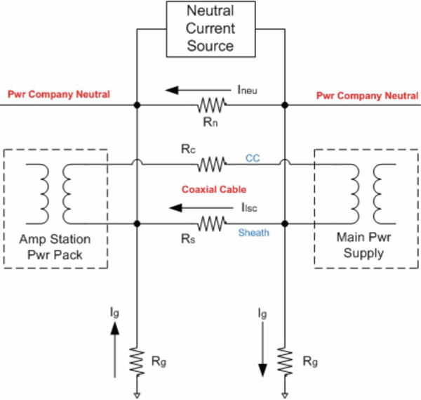
Figure 1. Basic LSC mechanism
Modeling calculations on additive (in-phase) induced voltages from LSCs are shown in Figure 2. Basic model assumptions are at the bottom of the figure. Line extender amplifiers 1, 2 and 3 are in a single cascade from the main AC power supply.
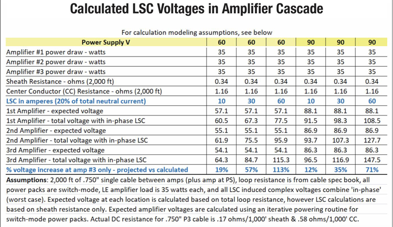
Figure 2. LSC model calculations
As shown in Figure 2, so-called ‘normal’ LSC values yield increased voltages when conditions are phase-additive. Under high LSC conditions, additive voltages can easily fire a transient protective device such as an AC crowbar circuit. Technically, cable television plant grounding does not create LSCs but rather the bonding process alone. However, additional grounds placed by the cable operator can, in certain instances, increase LSC currents. Therefore, the placement of extra grounds beyond basic bonding requirements should be performed judiciously and according to NESC guidelines.
Regarding the impact of LSCs in the cable plant, general problems are:
- Sheath currents may cause electrolysis and rectification in cable plants where dissimilar metal contacts exist. Beyond plant physical degradation, this can cause unusual problems that may exhibit as RF and/or AC symptoms.
- Safety concerns for plant personnel. Once suspected, LSC situations should be treated with caution regarding how subsequent current/voltage measurements are performed.
- Power pack failures from excessive over-voltage conditions at switch-mode (or linear mode) regulator circuitry. For specific power pack failure issues, please review my full article.
Solutions
- Inadequate grounding through poor electric utility grounding practices often escalate LSC conditions. In many systems, the percentage of imbalance current carried by the utility ground system is low, on the order of 10% or less! In this situation, attempt to work with the electric utility to achieve better grounding in problematic plant areas. When this is not possible, the operator can place, under certain restrictions, additional grounds in the cable plant. Remember, however, that some codes prohibit the placement of two ground verticals on the same utility pole, so you may face restrictions in where additional grounds can be placed.
- Utilize AC crowbar transient protection devices in general areas and at specific equipment where LSC (or transient) over-current/voltage conditions are a recurring problem. An AC crowbar fires (and resets) every half AC cycle at designated voltage levels, shorting excessive voltages from center conductor to sheath (and ground). Amplifier printed circuit board traces along with other components such as plant passives must be ruggedized to survive momentarily high currents that flow through the sheath/ground system.
- Convert remaining 60 VAC systems to 90 VAC. The calculations in this article along with past experience demonstrate that the impact of LSC induced voltages is reduced as supply voltages are increased.
- LSC conditions in jacketed aerial or underground plant present different challenges and are beyond the scope of this article.
In my Fall 2019 column I plan to review recommendations from the Plant Powering and Plant Protection Subcommittees of the Cable Television Laboratories Outage Reduction Task Force Report issued in the 1990s. These recommendations were broad in scope and application, and remain highly relevant to cable television plant operation and protection in 2019.
 H. Mark Bowers,
Cablesoft Engineering, Inc.
Mark is VP of Engineering at Cablesoft Engineering, Inc. He has been involved in telephony since 1968 and the cable industry since 1973. His last industry position was VP of Corporate Engineering for Warner Cable Communications in Dublin, OH. Mark’s education includes the U.S. Naval Nuclear Engineering School, and BS and MS Degrees in Management of Technology. Mark is a member of the SCTE, the IEEE, and is a Senior Member and licensed Master Telecommunications Engineer with iNARTE.
Credit: Charts provided by author