Measuring Cable TV Network Downstream RF Signal Levels (PART THREE)
By Ron Hranac
In this third installment of a three-part article, the discussion about measurement of downstream RF signal levels continues. Read part one here.
Making accurate signal level measurements is not quite as simple as it might seem at first glance. This installment concludes the discussion about various factors that can affect those measurements, and includes tips to ensure more accurate and reliable results.
Temperature — Temperature can have a significant effect on the accuracy of RF signal level measurements. As discussed previously, ambient temperature affects the attenuation of coaxial cable, which in turn can affect amplifier input and output RF signal levels. Temperature can affect test equipment calibration and measurement accuracy. Indeed, many test equipment manufacturers provide absolute accuracy specifications for both a fixed temperature and over a range of temperatures. For example, here is the published accuracy specification for a popular handheld cable field instrument:
@ 25 ˚C (77 ˚F): ±0.75 dB
Over temp -18 ˚C to +50 ˚C (0 ˚F to 122 ˚F):
±2.0 dB (analog), ±2.5 dB (digital)
Note the wider accuracy windows for analog and digital measurements over temperature compared to the specified accuracy at 25 °C (77 °F).
Single Channel-Per-Port versus Multiple Channels Per Port — If a QAM modulator supports multiple channels per RF port, it is important to keep in mind that per-channel maximum output signal level decreases when the modulator is operating in multiple-channel mode compared to operation in single-channel mode. Figure 7 is excerpted from Table 6.4 of the DRFI Specification.
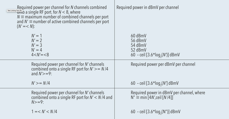
Figure 7. Excerpt from DRFI.
If a DRFI-compliant QAM modulator is configured for one channel per port, the maximum RF power for that channel is +60 dBmV. If the same modulator is configured for four channels per port, the maximum per-channel power is +52 dBmV. If the channel count per port is greater than four, the maximum per-channel power is defined by the formula4
60 – ceil[3.6*log2(N’)]
where
ceil is the mathematical ceiling function
N’ is the number of active channels per port
Note that the logarithm in the formula is base 2, not the more common base 10.
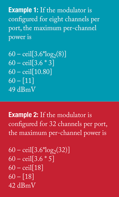
The following two examples illustrate the change in maximum per-channel signal level with different numbers of channels per port.
Assumption Errors
Don’t assume or estimate the amount of loss in cables, passives, etc., MEASURE IT. If the RF signal level on multiple frequencies or channels is being measured, be sure to measure the attenuation through cables and other components between the signal source and measurement device at those frequencies. Consider ALL losses in the signal path: coaxial cables (mini-coax and conventional-size coax), connectors and adapters, passives such as splitters and couplers, in-line attenuators, and test points. If gain is present in the signal path between the source and measurement device, that must be accounted for, too (measure it, don’t assume it).
Coaxial cable attenuation is not uniform across frequency — its attenuation is greater at higher frequencies than it is at lower frequencies. Even though passive devices such as splitters are generally assumed to have flat attenuation across a wide frequency range, in reality passive device attenuation at higher frequencies is usually at least slightly greater than it is at lower frequencies.
Tips for More Accurate Measurements
The following recommendations are provided to help ensure more accurate results when measuring downstream RF power.
Caution: Take appropriate precautions for electrostatic discharge (ESD) protection when performing the measurements described in this article. If the test equipment is powered from an AC mains connection, connect the test equipment to the same AC circuit as the equipment being measured.
- In scenarios where highly accurate RF signal level measurement results are required, be aware that some instruments may not have the required accuracy. For instance, many handheld field instruments have absolute accuracy specifications in the ±1.5 to ±2.5 dB range.
- Use test equipment that has been calibrated by the factory or a factory-authorized service center at intervals recommended by the manufacturer.
- Ensure that the measurement device has sufficient dynamic range to support the desired measurement. In some cases it might be necessary to use an external attenuator connected to the input of the measurement device to prevent instrument overload. If so, be sure to take into account the impact of the additional attenuation on the measurement results.
- Follow the signal source and measurement device manufacturers’ recommendations for adequate equipment warmup time prior to making RF signal level measurements.
- If the test equipment has a built-in calibration routine available, be sure to use it prior to performing measurements.
- Some instruments may require additional configuration steps for measurement of different types of signals (e.g., analog TV signal visual carrier levels versus QAM signals). In all cases, follow the test equipment manufacturer’s instructions for setup and operation.
- Ensure that battery-operated test equipment is fully charged prior to use.
- To the extent possible, minimize the use of adapters, which can degrade measurement accuracy.
- Ensure that all connectors have been properly installed on test cables, and are adequately tightened on mating interfaces.
- Check all connectors between the signal source and measurement device (e.g., signal source output, patch panel(s), headend combiner, etc.), and ensure that all are properly tightened.
- Unused RF ports on combining networks, splitters, couplers, and other devices should be properly terminated using suitable 75-ohm impedance terminators.
- When checking amplifiers, nodes, and headend or hub site equipment, ensure that all modules, line cards, and plug-in components and accessories are properly seated in their respective chassis slots, housings, and sockets.
- Where applicable, confirm that the configuration of the signal source (e.g., CMTS or QAM modulator) is correct prior to performing RF signal level measurements.
- For signal sources that support multiple channels per port, take into account the reduced power-per-channel with multiple-channel operation compared to single-channel operation.
- Be sure to add the net attenuation of the interconnection to the measurement device’s displayed signal level reading to determine the source output power. Be aware that the net attenuation of the interconnection might not be uniform across frequency.
- Don’t assume or estimate the amount of attenuation in cables, passives, etc., MEASURE IT at the frequency or frequencies of interest.
Caution: To reduce the possibility of damaging the MCX connectors on CMTS or other device line cards, avoid connecting the test equipment directly to the line card connector. Instead, connect the test equipment to the end of a downstream cable that is already connected to the line card, to a convenient test point, or the output of an external RF switch (if used). Be sure to account for attenuation between the line card’s output connector and test equipment input (if possible, measure the actual loss). In scenarios where a direct connection must be made to a line card’s MCX connector, carefully connect an MCX connector-equipped test cable to the line card port, ensuring that the test cable’s MCX connector is properly mated to the line card’s MCX connector.
Measurement Error Example
The following example illustrates the impact of various factors on measurement accuracy.
Assume that a QAM modulator is configured via its setup menu to generate a single QAM signal on CTA5 channel 117 (750 MHz to 756 MHz) at an output level of +50 dBmV (digital channel power). Figure 8 illustrates this example. The desire is to compare the configured output signal level with the measured output signal level. What is the worst-case measurement error?
If there were no measurement error, the modulator output would be exactly +50 dBmV, the coax loss exactly 0.92 dB, and the net input power to the test equipment exactly +49.08 dBmV. The instrument would display the net input power, or +49.08 dBmV. Adding back the loss of the 10 ft. length of coax, 0.92 dB, to the reported signal level would yield the modulator’s +50 dBmV output level.
In reality, several factors will affect the test equipment’s reported measurement results. First, the modulator’s ±2 dB calibration accuracy means the actual output signal level could be anywhere in the +48 dBmV to +52 dBmV range when the device is configured for +50 dBmV. The coaxial cable’s actual loss at 750 MHz could be anywhere in the 0.72 dB to 1.12 dB range. The test equipment’s reported signal level could be as much as 2 dB below or above its actual net input power.
In a worst case scenario, all of the measurement errors would be at their extremes in the same direction and add constructively. For example, the modulator’s actual output signal level might be +48 dBmV, the cable loss 1.12 dB, and the test equipment accuracy at the –2 dB point. Thus, the net input signal level to the test equipment would be +48 dBmV – 1.12 dB = +46.88 dBmV. However, instead of reporting +46.88 dBmV, the instrument would report 2 dB low, or +44.88 dBmV. Adding back the assumed loss of the coax (0.92 dB) would mean the assumed modulator output signal level is +45.8 dBmV. If the actual cable loss (1.12 dB) were known, the assumed modulator output level would be +44.88 dBmV + 1.12 dB = +46 dBmV, or 4 dB below the configured output.
Practically speaking, the measurement errors are unlikely to be at their extremes, and even if they were, the errors probably would not all be in the same direction. There is a method known as root sum of squares, or RSS, that can be used to combine measurement errors (and uncertainties) and provide a more realistic total error or uncertainty. However, RSS is beyond the scope of this article. See [3] and [4] for more information on RSS.
Conclusion and Recommendations
Measurement of a cable network’s downstream RF signal levels is often taken for granted and assumed to be fairly straightforward. Rarely, however, is accurate signal level measurement as simple as connecting a piece of test equipment to a test point or signal source output connector.
Some important factors must be taken into consideration, such as measurement device absolute measurement accuracy compared to the accuracy of the signal source. Typical handheld field instruments are fine for most routine plant and subscriber drop measurements, but generally don’t have the necessary accuracy to confirm whether a CMTS or QAM modulator meets published specifications. For example, one cannot use a measurement device with a published accuracy spec of ±2.5 dB to accurately measure a signal source whose published RF output level accuracy is, say, ±1.5 dB.
Other factors discussed in this article must be accounted for when performing RF signal level measurements, all of which will affect a measurement device’s reported signal level. For more in-depth information about measurement of RF signal levels, the reader is encouraged to review some or all of the material listed in the bibliography.
—
Bibliography:
[3] “Fundamentals of RF & Microwave Power Measurements,” Agilent Application Note 64-1C (http://cp.literature.agilent.com/litweb/pdf/5965-6630E.pdf)
[4] “Power Measurement Basics,” Agilent PowerPoint presentation (http://www.keysight.com/upload/cmc_upload/All/BTB_PowerBasics_2005.pdf)
—
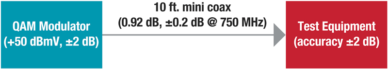
Figure 8. Block diagram for measurement error example.
—
- A multiple-channel-per-port QAM modulator operates with the functional equivalent of a built-in headend combiner, reducing the per-channel signal level as the number of channels increases (much like an actual combiner does). The 3.6*log2 term in the formula is intended to represent the QAM modulator’s equivalent internal splitter/combiner loss.
- The CTA channel designation refers to the Consumer Technology Association standard “Cable Television Channel Identification Plan CTA-542-D (Formerly CEA-542-D).”
 Ron Hranac
Technical Leader,
Cisco Systems
Ron Hranac, a 45-year veteran of the cable industry, is Technical Leader for Cisco’s Cable Access Business Unit. A Fellow Member of SCTE, Ron was inducted into the Society’s Hall of Fame in 2010, is a co-recipient of the Chairman’s Award, an SCTE Member of the Year, and is a member of the Cable TV Pioneers Class of ’97. He received the Society’s Excellence in Standards award at Cable-Tec Expo 2016. He has published hundreds of articles and papers, and has been a speaker at numerous international, national, regional, and local conferences and seminars.