Taps: A Peek Under the Hood
By Ron Hranac
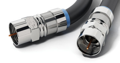
The nature of the architectures used in the cable industry’s radio frequency (RF) distribution networks means that some mechanism is necessary to connect hardline feeder cables to subscriber drop cables. That connection is accomplished using a (usually) passive device called a tap, line tap, or multi-tap. The most common type of tap is one that comprises a combination of directional coupler and splitter, a general design that has been around for decades.
Looking back
According to [1], among the earliest tap designs was Jerrold’s Model 1401, which was little more than a small metal box with three female C-type connectors (the predecessor to today’s F connectors). The internal circuitry was a simple tee, with a capacitively coupled tap. Installing one was service-disruptive, requiring cutting and connectorizing the coax (usually RG-59 or RG-11 type cable), reconnecting the feeder and hooking up the drop.
Next came the pressure tap, which did not require completely cutting the feeder to install. Entron patented the pressure tap in 1954, and named theirs the FasTee. The device used a capacitor or resistor for impedance matching. A variation of the design available from a number of manufacturers was known as a back-matched pressure tap, which incorporated additional components to improve the impedance match, although the match was never very good.
Pressure taps were notorious for signal leakage and ingress, weatherproofing issues, and if loose, degraded signal level.
To install a pressure tap, a metallic fixture was clamped onto the cable (prongs contacted the shield), and the pressure tap screwed into the fixture after drilling a small hole in the cable’s jacket and shield to reach the center conductor. Examples of pressure taps can be seen here: http://theoldcatvequipmentmuseum.org/160/163/1633/index.html
There had to be a better approach. There was: Jerrold’s Ken Simons developed the directional coupler (DC) tap in the mid-1950s. Simons was a prolific inventor of a lot of technology used by the cable industry. The Cable Center has a variety of his prototypes in their archives.
Directional coupler-based taps
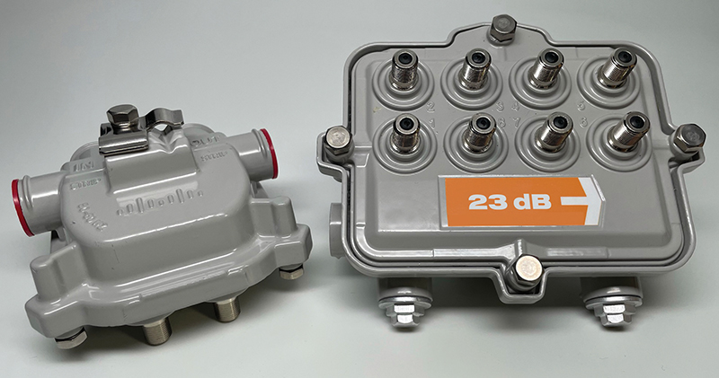
Figure 1 illustrates a simplified block diagram of a typical DC-based tap. The DC at the top center of the figure couples or taps some of the signal from the feeder, with the coupled leg of the DC connected to a two-way (shown), four-way, or eight-way splitter. The total insertion loss from the tap’s INPUT port to each TAP PORT determines the nominal tap value. For example, a 20 dB two-port tap comprises a 16 dB directional coupler and a two-way splitter. Not shown in the figure are components for AC bypass, which routes 60 or 90 VAC line current around the DC between the INPUT and OUTPUT ports. The housing’s INPUT and OUTPUT ports have 5/8-24 threads for hardline connectors, and the TAP PORTS are female F connectors. A detailed overview of the inner workings of taps can be found in [2].
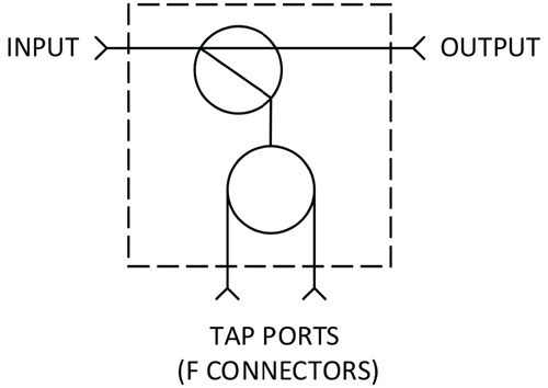
Figure 1. Block diagram of a directional coupler-based tap.
Most taps are passive, but active taps have been available, too, including addressable versions. Some allowed service to be turned on/off remotely, and others incorporated conditional access technology (interdiction, switchable filters, etc.).
Some tap designs support passing limited electric current from the feeder into either the drop cable or a separate twisted-pair to power on-premises devices.
To terminate or not terminate?
If a DC-based tap is installed at an end-of-line location, the OUTPUT port must be terminated using a 75 ohms impedance chassis terminator. The exception is the so-called self-terminating tap, available in 4 dB two-port, 8 dB four-port, and 11 dB eight-port values. The phrase “self-terminating” causes a lot of confusion, because the tap itself does not terminate the feeder in the 75 ohms nominal impedance of the network. Figure 2 shows a simplified block diagram of a 4 dB two-port tap. Note that there is no DC; the INPUT port is connected directly to the two-way splitter. In 8 dB four-port and 11 dB eight-port taps, the INPUT port is connected directly to four-way and eight-way splitters respectively.
How, then, can one terminate the feeder when a self-terminating tap is installed at an end-of-line location? The answer is to install 75 ohms impedance F-type terminators on all of the TAP PORTS (unless, of course, active drops are connected to those ports). I’ve seen some install a chassis terminator on the tap housing’s OUTPUT port, which is unnecessary and doesn’t connect to anything. Most self-terminating taps use the same kind of housing as DC-based taps, and have a 5/8-24 threaded port, center conductor seizure mechanism, etc., on the OUTPUT port side. However, there is no electrical connection between the faceplate’s splitter circuitry and the OUTPUT port.
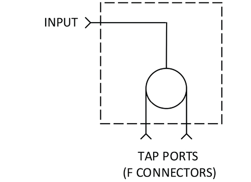
Figure 2. Block diagram of a 4 dB two-port self-terminating tap.
What about terminating unused TAP PORTS? Some operators don’t terminate them on any value tap; others terminate unused TAP PORTS on low value taps but not high-value taps. My recommendation is to terminate all unused TAP PORTS.
Conditioned taps
As cable network operating RF bandwidth increases, it becomes more difficult to manage forward and return signal levels in the subscriber drop. One solution is to use what are called conditioned taps, which enable optimization of drop signal levels without impacting feeder signal levels. A small passive plug-in is installed between the coupled leg of the internal DC and the splitter. The rectangle with an asterisk in Figure 3 is where the plug-in is installed. The plug-in can be a cable equalizer, cable simulator, return path attenuator, etc., depending on desired signal conditioning.
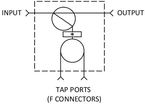
Figure 3. Block diagram of a conditioned tap.
Wrapping up
Today’s DC-based taps support much wider RF bandwidths, higher through-current capacity, the ability to condition drop levels, and more. If Ken Simons were still with us, he would likely be smiling, knowing that his basic tap design continues to be used more than six decades later.
[1] History Between Their Ears, by Archer S. Taylor, © 2000 The Cable Center, ISBN 1-89182-101-6
[2] Chapter 10 of Modern Cable Television Technology, 2nd Ed., by Walter Ciciora, James Farmer, David Large, and Michael Adams; © 2004, Morgan Kaufmann Publishers, ISBN 1-55860-828-1
 Ron Hranac
Technical Editor,
Broadband Library
rhranac@aol.com
Ron Hranac, a 49+ year veteran of the cable industry, has worked on the operator and vendor side during his career. A Fellow Member of SCTE and co-founder and Associate Board Member of the organization’s Rocky Mountain Chapter, Ron was inducted into the Society’s Hall of Fame in 2010, is a co-recipient of the Chairman’s Award, an SCTE Member of the Year, and is a member of the Cable TV Pioneers Class of ’97. He received the Society’s Excellence in Standards award at Cable-Tec Expo 2016. He was recipient of the European Society for Broadband Professionals’ 2016 Tom Hall award for Outstanding Services to Broadband Engineering, and was named winner of the 2017 David Hall Award for Best Presentation. He has published hundreds of articles and papers, and has been a speaker at numerous international, national, regional, and local conferences and seminars.