
Optical Dispersion
By Steven Harris
Optical networks and the performance management of their signals are a key foundation in the telecommunications industry achieving the goals of the 10G platform. Operators are evolving networks that use analog intensity modulation (AIM) data, as well as new distributed access architectures (DAA) and passive optical networks (PON) that leverage digital binary encoded data. Optical signal transmission has always been limited by optical dispersion, an area that is important to understand and characterize in our optical networks.
Dispersion is the spreading or smearing (Figure 1 Part 1) of a light pulse over time (picoseconds/ps) and distance (kilometers/km), or as it travels over an optical link. Dispersion may change from one measurement to another, impacting the ability for a receiver to distinguish a discrete light pulse properly. The pulses reach a destination using different timing or at a different velocity. The effect of dispersion will reduce the overall capacity of a fiber link, thus lowering the bit rate. In networks like 10G and beyond, dispersion may be more of an issue as the light pulses become smaller. There are several types of dispersion to be aware of in our networks:
- modal dispersion
- chromatic dispersion
- material dispersion
- waveguide dispersion
- polarization mode dispersion
The first type of dispersion is known as modal dispersion, allowing a light pulse to break up into different modes or different paths. Modal dispersion occurs in multimode optics, where the pulse will spread in time and distance due to multiple modes of light. Single mode fiber (SMF) with one mode of light has no issues with modal dispersion.
A second type of dispersion that is important to our access networks is chromatic dispersion (CD), measured in picoseconds (ps) per wavelength (nm) x distance (km). This type of dispersion with multiple wavelength components and different colors of light, causes light pulses to travel at a slower velocity than in a vacuum (c = 299,792 km/s). The velocity of a wavelength and the color of light is directly related to the refractive index of a fiber, where longer wavelengths or lower frequencies travel slightly faster. A light pulse that travels at different velocities causes spreading of the pulse or pulses to overlap (Figure 1 Part 1) with one another, resulting in bit errors and dB loss. In turn, shorter wavelengths (higher frequencies) may intermix with the longer wavelengths of an adjacent pulse, leading to distortion and noise that create inter-symbol interference (ISI). Total CD is the summation of material dispersion and waveguide dispersion, where typical ITU-T G.652 SMF dispersion is 17 ps/1550 nm x km and a maximum of 738 ps/nm x km for 10G Ethernet.
Material dispersion is caused by the variation of the refractive index of a given material in SMF. The silica of the fiber is wavelength dependent and the materials will cause a pulse to travel at different velocities. We are not able to change material dispersion as it is fixed, as well as directly related to the refractive index of the fiber. It is important to collaborate with experienced vendors within our society that provide quality cabling.
Waveguide dispersion in SMF is where the light pulse exceeds the diameter of the fiber’s core (Figure 1 Part 3), and part of the light pulse travels in the cladding. The wider distribution of the pulse is known as mode field diameter (MFD). Due to the lower refractive index of the cladding, light will travel at different speeds in the core and cladding. In addition, since power is a function of the wavelength, the amount of power distributed in the cladding and core will determine the amount of dispersion. Longer wavelengths and lower frequencies, will distribute more power in the cladding. Specialty fibers have been created to alter a fiber’s refractive index profile, achieving different amounts of waveguide dispersion. Material dispersion and waveguide dispersion have opposite variations based on wavelength. Quality design and altered refractive index profiles have a zero-dispersion wavelength (ZDW), where the wavelength of material dispersion and waveguide dispersion cancel one another.
Polarization mode dispersion (PMD) is a random effect due to imperfect fiber geometry, flawed connectors, and poor splices within long SMF links. In addition, continuously fluctuating temperatures and wind stresses are common causes of bi-refringence (Figure 1 Part 4) in older aerial fibers, thus may add to PMD. Remember optical electric fields and magnetic fields are perpendicular, as well as being perpendicular to the direction of how the pulse will travel, as shown in Figure 1 Part 2. PMD may cause the MFD to include more cladding in one polarization, this portion of the pulse will experience slight delays in velocity. Overall, PMD is wavelength dependent, typically well controlled in current fiber optical cables. PMD has not been a significant issue at the bit rates up to 10G, but with a maximum value for PMD of 24 ps in 40G and 100G systems it may become more of a concern in the future. PMD is measured in ps/sqrt(km) and for G.652A is less than .5 ps/sqrt(km).
It is important to collaborate with our vendor community, the SCTE·ISBE standards programs and stay well-educated in the area of fiber optics with SCTE·ISBE offered resources. The popular ITU G.652A was originally developed in the ’80s and 19 different SMF ITU standards exist. Many reduce dispersion in optic cables like ITU G.652A, G.653B or G.655. Understanding these standards and their differences will allow you to have the proper conversation with your vendor partners and select the top options for your network. In addition, properly characterizing existing access network optic cables using proper test and measurement tools for CD and PMD will ensure your network will grow in the right direction in the future. Finally, there are dispersion compensation modules available for CD and PMD, and these may be an option as well.
—
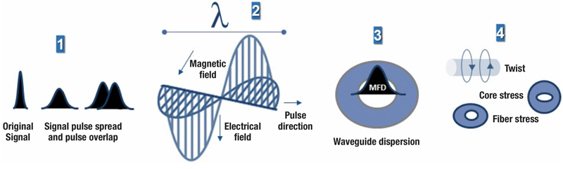
Figure 1. Light pulses (1); optical fields (2); waveguide/MFD (3); and bi-refringence (4)
—
 Steven Harris
Executive Director, Technical Sales, Learning & Development
SCTE•ISBE
sharris@scte.org
Steve is an international SME and thought leader, and the executive director of education and business development for SCTE·ISBE. He is responsible for overseeing the architecture and evolution of educational programs, credentialing, and customized career progressions, as well as business development and partnerships. His team is responsible for an education library that is now 900+ modules, designed to drive business results. With more than 30 years in education, he has taught much of the content of the library, with a dynamic approach to the delivery of highly complex topics.
Shutterstock