Loss
By Ron Hranac
Gain and loss are seemingly straightforward parameters we’ve dealt with in our cable networks since the industry got its start in the late 1940s. Let’s look a little more closely at one of those parameters: loss. The SCTE operational practice SCTE 270 2021r1 Mathematics of Cable (https://www.scte.org/standards/library/catalog/scte-270-mathematics-of-cable/) includes the following definition: “Loss (or attenuation) is a decrease in the power of a signal or signals, usually measured in decibels.”
Mathematically, lossdB = 10log10(Pin/Pout), where lossdB is the attenuation in decibels (dB) through a device, component, cable, etc., and Pin and Pout are the input and output power in watts. Loss occurring when a signal passes through a device or component is often called insertion loss. Note that insertion loss in dB is a positive value, and a larger positive value when there is more insertion loss. Figure 1 shows an example of an attenuator with about 3 dB (actually 3.01 dB) of insertion loss.
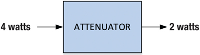
Figure 1. The loss through the attenuator is 10log10(4 watts/2 watts) = 3.01 dB.
When signal power is expressed in dBmV, the math is simple subtraction: lossdB = Pin(dBmV) – Pout(dBmV), where lossdB is the attenuation in decibels as before, and Pin(dBmV) and Pout(dBmV) are the input and output signal levels in dBmV. Figure 2 shows an example of an attenuator with 6 dB of insertion loss.
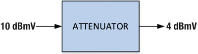
Figure 2. The loss through the attenuator is 10 dBmV – 4 dBmV = 6 dB.
Generally speaking, we deal with three main types of radio frequency (RF) loss or attenuation over the wide frequency ranges of our cable networks: flat loss, cable loss, and equalizer loss. Yes, there are other types of loss, but here I’m focusing on these three, approximations of which are illustrated graphically in Figure 3. On the left side of the figure, the test signal being used to characterize loss comprises several equal-amplitude carriers across a frequency range of interest (a continuous broadband sweep signal could also be used). The test signal is injected into the input of the device or component being measured. On the right side of the figure, the effects of the three types of loss can be seen.
Flat loss
When we think of flat loss, we often assume equal loss-versus-frequency in passive components or devices such as connectors, splitters, directional couplers, plug-in pads (attenuators), and so on. In reality, flat loss isn’t exactly the same at all frequencies. It’s not unusual to see a small amount of amplitude ripple and/or other non-flatness throughout the passband, and somewhat greater loss at higher frequencies than at lower frequencies. Regarding the latter, a typical two-way drop splitter, for instance, has about 3.5 dB of insertion loss at 55 MHz and 4.2 dB of insertion loss at 1 GHz.
Cable loss
Loss through a length of coaxial cable is greater at higher frequencies than at lower frequencies. A 100 ft. length of commonly available Series 6 drop cable has a published loss of 1.60 dB at 55 MHz and 6.55 dB of loss at 1 GHz. The cable loss at any frequency is proportional to the length of the cable, so that a 200 ft. length of coax will have twice the loss (in dB) as a 100 ft. length of the same cable, at the same frequency. A 300 ft. length of the cable will have three times the loss (in dB) as a 100 ft. length of the cable, and so on.
What causes cable attenuation to be greater at higher frequencies than at lower frequencies? A significant contributor is resistive losses in the cable’s metallic conductors. The resistive losses of coaxial cable are larger when the effective cross-section area of the conductors is smaller; an analogy is water flowing through a smaller pipe compared to a larger pipe. The resistive losses—think AC resistance, which is not the same as the DC resistance one measures with a conventional ohmmeter—are related to skin effect. Skin effect (and skin depth) means the effective cross-section of the center conductor and shield is less at higher frequencies than at lower frequencies, making the effective AC resistance greater at higher frequencies. The dielectric also plays a factor in cable loss. For more about all of this, see my article “Coaxial Cable Attenuation” in the Summer 2021 issue of Broadband Library (https://broadbandlibrary.com/coaxial-cable-attenuation/).
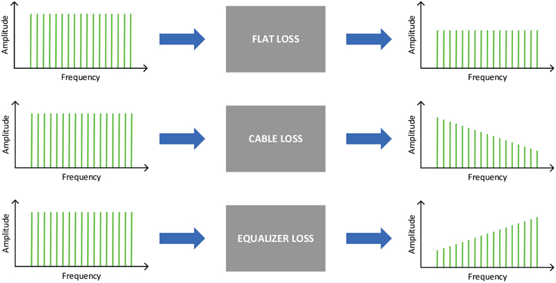
Figure 3. Examples of three types of loss that can occur in cable networks.
Equalizer loss
As just discussed, coaxial cable attenuates higher frequencies more than lower frequencies. After RF signals pass through several hundred feet of cable between, say, the output of a node and the input to a line extender, signal levels in the RF spectrum will have a downward tilt as illustrated in the “cable loss” row of Figure 3. Ideally, the signal levels across frequency at the line extender input should be flat. Plug-in equalizers are used to “cancel” the tilt caused by the cable (in-line equalizers are also used in the coax distribution network for a similar reason). How? The plug-in equalizers are passive circuits or components that have approximately the opposite loss-versus-frequency characteristics of coaxial cable, an upward tilt as shown in the bottom row of Figure 3, resulting in a nominally flat amplitude-versus-frequency spectrum at the input to the line extender’s internal gain stages. For instance, a 9 dB plug-in equalizer for a widely used series of amplifiers has 8.4 dB of loss at 52 MHz and 1.0 dB of loss at 1.2 GHz.
What happens to the “lost” RF?
There is some “it depends” in the answer. Where resistance is involved—such as the effective AC resistance in metallic conductors, etc.—the lost RF power is usually dissipated as heat.
With devices such as two-way splitters, things are a bit more complicated. In an ideal two-way splitter, all of the input RF power is divided equally between the two outputs, so the RF power isn’t actually lost. Half of the original power goes to one output port, and half goes to the other output port; that accounts for 3.01 dB of the ideal splitter’s insertion loss. Real-world two-way splitters have an additional 0.5 dB to 1 dB or so of loss, which is mostly caused by resistive or ohmic losses (i.e., conversion to heat) in the toroidal transformers’ ferrite-core material and their very small gauge wire windings. So, some of the power is dissipated as heat, while most of it passes to the two output ports. This same principle applies to unbalanced splitters, directional couplers, and other passives.
RF power loss also occurs because of impedance mismatches, which cause some of the power incident upon those mismatches to be reflected back toward the sources. The difference, in dB, between the incident and reflected power is called return loss; see “Return Loss” in the Spring 2017 issue of Broadband Library (https://broadbandlibrary.com/return-loss/). Pretty much every RF component in our networks introduces an impedance mismatch to some degree, although in a properly operating and maintained network those mismatches are kept small and aren’t usually of serious concern. Still, some RF power is lost because of them.
Interestingly, many filter designs operate on the principle of having low return loss (a poor impedance mismatch) in the stopband frequency range, which reflects a large fraction of the power in that frequency range. The filter’s passband has high return loss (a good impedance match), which passes most of the desired power, reflecting only a small fraction of the input power at these frequencies. Some filter designs absorb and dissipate as heat power in the stopband range, rather than just reflecting the power.
Sometimes RF power in a cable network is lost to the over-the-air environment as signal leakage.
Wrapping up
Managing RF losses in our cable networks is important. We normally offset losses with gain provided by active devices, which can be a bit of a balancing act (see what I did there?). When impairments come into play, losses can become, um, interesting. Examples include rolloff, suckouts, and other types of losses we don’t want!

Ron Hranac
Technical Editor,
Broadband Library
rhranac@aol.com
Ron Hranac, a 51 year veteran of the cable industry, has worked on the operator and vendor side during his career. A Fellow Member of SCTE and co-founder and Assistant Board Member of the organization’s Rocky Mountain Chapter, Ron was inducted into the Society’s Hall of Fame in 2010, is a co-recipient of the Chairman’s Award, an SCTE Member of the Year, and is a member of the Cable TV Pioneers Class of ’97. He received the Society’s Excellence in Standards award at Cable-Tec Expo 2016. He was recipient of the European Society for Broadband Professionals’ 2016 Tom Hall Award for Outstanding Services to Broadband Engineering, and was named winner of the 2017 David Hall Award for Best Presentation. He has published hundreds of articles and papers, and has been a speaker at numerous international, national, regional, and local conferences and seminars.
Images provided by author.