The Broadband Mechanic and Layer 1 Physical
By Thomas J. Gorman
While companies scramble to create higher skilled technical personnel, the need for basic skills may get left in the dust. With so much attention on Layer 2 (switching), Layer 3 (routing) and higher, there’s a good chance that Layer 1 (physical) gets little attention. If you look at the titles given to new hired service and install personnel, invariably they are called “techs” (Broadband Tech, or Commtech, to name a few). But I wonder if the start point should be as a “mech,” to ensure that the finer points of making good physical connections are focused on, and then once that proficiency is achieved, the promotion to “tech” can occur.
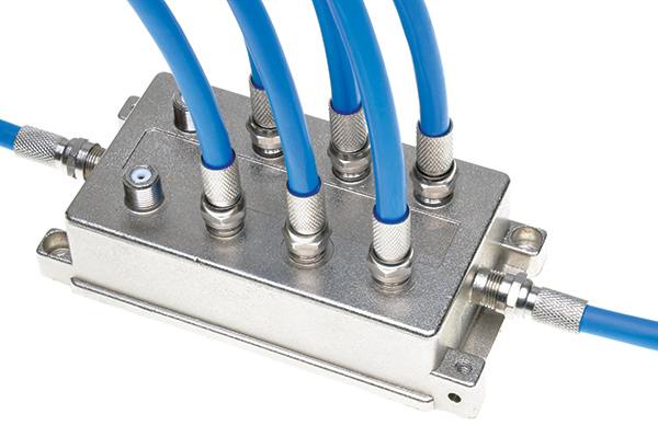
Between a headend and a customer, there’s no lack of things that can go wrong. IP configurations, QAM modulator failures, digital insertion gear, and streaming servers all have their hiccups. But consider that between the headend and the customer, there are potentially hundreds of failure points that require tender loving care. Following that path to the customer, there are fiber connectors, jumpers, splices, coax connectors, taps, drop hangers, siding clips, ground lugs, heat shrink, and RJ-45 connectors, all presenting a problem waiting to happen.
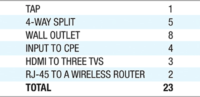
In a typical customer’s home, with an average of four outlets, let’s count the number of physical connectors. With splitters, wall outlets, HDMI cables, and even Cat5 from a modem to a wireless router, 23 (or more) opportunities to fail exist in any one home.
The effort to make good connectors is assisted by good tools and it truly is hard to make a bad connector nowadays. But there’s a caveat to that. Tools must be maintained! Replacing blades in a cable prep tool is the most important thing that an installer or service tech can do to make good connectors, but also taking time in team meetings to verify that tools are in good working condition makes sure that good connectors will be installed. Compression tools do wear out and may not compress the ferrule correctly. Finally, the 7/16 wrench is a tech’s best friend for making tight connections.
Why? Making a good physical contact reduces the likelihood of signal loss. The higher the frequencies, the more the signal rides on the surface of the coax center conductor (the “skin effect”). A nick in that center conductor will interrupt electron flow, and can cause signal issues, and packet loss.
Weatherproofing an outside connector is an obvious step to keep the cable and connector in a pristine state. Water migration into a cable will drive a customer (and a tech) crazy with intermittent issues for a long time. This water migration creates a breakdown in shielding integrity, creating opportunities for signal leakage and ingress of interfering signals. When a repeat customer has regular resolution codes of “replaced outside connector,” that can be a clue that it’s time to replace that drop.
Manufactures have created connectors that maintain a good connection even when the connector is loose (primarily aimed at solving issues related to self-installs), but techs should not leave them to chance. Always make sure that connector is tightened every time. I will also suggest that on the opposite side of this situation is one in which techs will replace connectors arbitrarily, hoping that will solve a problem. I’ve actually ridden with techs who replaced every connector in a home, a week after a previous tech did the same thing. Why? A lack of trust in the previous tech’s connectorization skills! There’s an opportunity for teams to evaluate each other’s test connectors and build that trust.
The “C” in HFC is the weakest link of the network.
In the distribution network, there can be 20 hardline connectors between a node and a customer. As before, tools must be in good shape to make good connections. Techs damage hardline cables by using a metallic blade, resulting in loss of copper and negatively impacting the skin effect. Many techs use drills with their coring tools which give a false feeling of quality in the tools. Blades should be evaluated and replaced as necessary. Weatherproofing those connectors with heat shrink keeps them in good condition, but in haste, techs will turn up the heat to speed up the heat shrink process, without considering that excessive heat may be melting the coax dielectric and degrading the cable’s impedance.
Fiber
Contamination is the number one killer for all things fiber. Where there is a connector, there is the opportunity for contamination, and it can be an insidious problem. Consider using test equipment to evaluate networks, such as optical time domain reflectometers (OTDRs), optical spectrum analyzers (OSAs), etc. The jumper on that device should be cleaned before each test to ensure that the test is as accurate as can be, and more importantly, that the fiber connecting to the transmitter (or receiver) doesn’t get contaminated just by connecting to the test jumper. I have noticed where companies have invested in proper cleaning kits as they’ve grown networks, but that there isn’t an ongoing purchase of cleaning equipment, which can be an indicator that technicians may be haphazard with maintaining the integrity of its fiber terminations.
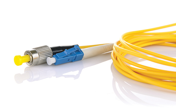
A particle that partially or completely blocks the core generates strong back reflections, which can cause instability in the laser system. A 1-micrometer dust particle on a single-mode core can block up to 1% of the light (a 0.05 dB loss). As a matter of fact, a 9-micrometer speck is still too small to see without a microscope, but it can completely block the fiber core. These contaminants can be more difficult to remove than dust particles.
Contamination in the optical connection can cause a component failure or certainly a system failure. My war story is troubleshooting a headend in the mid 1990s with 3000 mechanical terminations. Every node being served from this headend was registering a signal-to-noise ratio (SNR) of anywhere from 3 to 6 dB worse than calculated. I asked the system engineer for a fiber scope to look at connectors, and his response was, “A fiber what?” Needless to say, after acquiring a fiber scope we found that all 3000 terminations were contaminated by a dirty OTDR jumper. The very piece of test equipment used to verify the integrity of the network was in fact, ruining that integrity!
With the incredible volume of fiber connections in the field, proper handling and dressing of fibers in cabinets and enclosures is complicated. There are going to be more hands than ever touching enclosures, splice trays, and storage devices. That means more opportunity for microbends, increasing attenuation, and weakening the fiber itself.
Nowhere in this discussion is DOCSIS® 3.1, remote PHY, dense wavelength division multiplexing (DWDM) and advanced architectures. That’s because none of them work if the physical continuity of cable (outside and inside plant) and fiber is not working. So is it time to brush up on mechanical skills? Look at the topics where you are spending your time training, and where you are spending the most time resolving customer problems. It might be a clue!
1 Inspection and Cleaning Procedures for Fiber-Optic Connections, Cisco Systems, Document ID 51834, Nov. 30, 2016.
 Thomas J. Gorman
President, opXL, LLC.
In February 2012, Tom started opXL, LLC to support companies in improving all facets of operations. Customers range from small software development companies to Fortune 100 telecommunications companies. Tom has authored numerous articles on workforce management, automation and dynamic dispatching. He served on the SCTE Board of Directors for 6 years and was its chairman from 2007 to 2009. Tom was inducted into the SCTE Engineering Hall of Fame in 2007, was named SCTE Member of the Year in 2011, and joined the Cable TV Pioneer class of 2015. Tom has served on the Board of Directors for the Rocky Mountain Chapter of SCTE for 6 years and was named chapter president in 2017.
Credit: Shutterstock