Fiber Monitoring: Good For Your System
By Neal Y Nakamura
Outside plant fiber outages are notorious for their unpredictable times to repair. Delays in dispatching the repair crews are common in the traditional method because of the step-by-step sequence of tasks and handoffs needed to recognize plant damage, locate it and direct truck rolls. When network alarms sound, the inside plant equipment is checked first. If no problems are found, then the cause defaults to the outside plant cabling, and troubleshooting teams are deployed to pinpoint the damage site. Trucks roll when it is found. The analysis and search process can go quickly… or not.
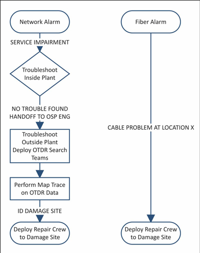
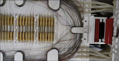
[Fig 1] A fiber monitor is an automated alternative. It is a pre-deployed troubleshooting system that detects cable damage immediately and simultaneously provides the location information needed to dispatch the trucks.
A fiber monitor is a network of software controlled optical time domain reflectometers (OTDRs) that measure the optical transmission characteristics of the fiber strands at the physical layer. Only the condition of the glass is tested and not the condition of the network transmission equipment. The automated software compares each measurement against a reference database of normal conditions and notifies by text, email and SNMP messages whenever any variances occur.
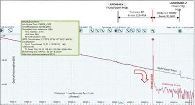
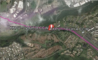
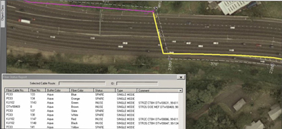
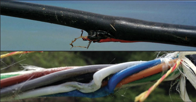
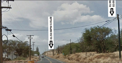
[See Fig 2] The basic message content includes loss measurements and distance, and a hyperlink to the monitor software application. With user input, the message content may include fiber panel, port, strand assignments, latitude-longitude positions and KMZ (Keyhole Markup Language Zipped, Google Earth-viewable) map file attachments containing aerial views of the impairment locations and cable routes.
Implementation Strategy
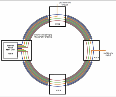
Fiber monitor deployment is a performance-to-cost compromise of remote test units, test port counts and fiber strands tested to cost. Testing may be as minimal as monitoring single fiber strands along critical cable routes to detect high impacting, completely severed cable damage. Or, it may be progressively more comprehensive to detect less catastrophic damage by testing strands in individual cable sheaths in multi-sheath bundles, testing cross sectional regions of the cables, and testing live fibers that carry critical traffic. Assigning two test ports per ring route in a counter-rotating configuration will bracket multiple or extended-length breaks by measuring the rings from both ends. [Fig 5] Dispersing multiple test strands over a cable’s cross section will help to differentiate partial damage or kinks from complete cable breaks. Installing loop-backs on point-to-point links multiply a cable’s cross sectional detail coverage without encumbering additional test ports. Testing multiple strands along each route also permits temporary rerouting of test ports when needed to troubleshoot unmonitored strands without completely disabling the critical transport monitor function. On-demand tests may be connected by any technician qualified to install fiber patches in a hub. Qualified OTDR operators may examine the fiber remotely.
Testing in-service fiber strands that carry critical services is arguably the most effective use of a fiber monitor. The 1650 nanometer (nm) OTDR wavelength may be used to monitor most digital and analog optical systems. Any mishandling or damage to the most important strands will generate alarms. Paired fiber transmit-receive systems may be tested in directions opposite the signal flow to eliminate the chance of the OTDR laser pulses interfering with services. Passive optical networks and other bidirectional systems may be monitored in specialized configurations. In-service testing requires the installation of bypass and blocking filters to couple the test signals into the live fiber. Insertion losses of the filters must be accommodated in the network designs.
Proactive Maintenance
The robotic 24 by 7 testing of the network cabling provides a fast response to fiber damage. The constant reference checks will also detect minor impairments before they become major outages. When configured for testing at the 1650 nm wavelength, the system is more sensitive to compression, heat and bends in the fiber strands than standard transmission equipment operating in the single mode communications spectrum of 1270 nm through 1610 nm. Minor fiber alarms trigger on low level impairments well in advance of other network alarms.
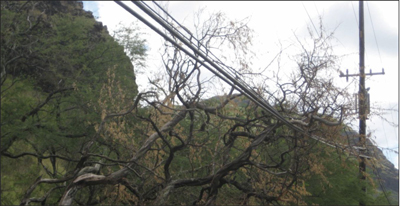
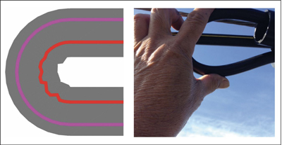
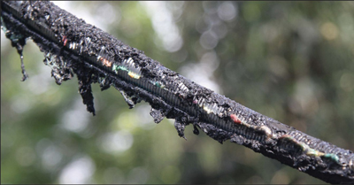
A minor alarm from one side of the cable and not the other indicates a kink [Fig 7] or a partial cable sever if major. Cable installations that snag, compress or kink a monitored cable will trigger alarms, possibly early enough to stop the job before damage and service disruptions occur. Improperly routed fiber strands on the splicing bench trigger alarms that will be read by splicing teams and be remedied on the spot. [Fig 8] A leaning tree in gusty winds that gradually erodes through a cable can be differentiated from a motionless fallen utility pole lying on a fiber cable by the multiple macro bend alarms of changing attenuation generated by the moving tree versus a single notification generated by the static pole. To dispatch a repair crew at 3 a.m. and save a cable or wait until morning because it won’t make any difference can be an informed manager’s judgement call.
User Input
User input shapes the quality of the fiber monitor’s translations from its optical measurements into physical locations in the outside plant. Alarm file attachments that include accurate maps and details such as splice locations, port assignments and fiber identifications are the user’s responsibility. Documenting optical to physical route differences and inserting landmark references are a part of the calibration process. KMZ fiber route files and landmarks needed to graphically indicate damage sites require spatial data processing to prepare. Fiber monitor support staffing should include skillsets in geospatial information processing, fiber design and construction methods, and OTDR trace interpretation.
Conclusion
A fiber monitor saves critical hours by automating the initial steps in the classic fiber restoration fire drill, ensuring prompt and accurate repair crew truck rolls. Its ability to proactively detect potential outages adds a new dimension to outside plant fiber maintenance. Accurate, comprehensive supporting data, optimum network coverage and competent alarm interpreting skills are key ingredients in building and operating a high performance fiber monitor. It validates itself irregularly and unexpectedly. Its returns in labor and reduced network down times accumulate with each event.

Neal Y Nakamura
Mgr, Engineering Information
Charter Communications
Mililani, Hawaii
neal.nakamura@charter.com
Neal joined the SCTE in 1987 and has been a member of the engineering staff in Hawaii for 30 years. He has committed much of that time to strategic network planning, ‘tinkering’ in outside plant design, and applying geospatial technology in operational support. He received a BSEE from the University of Hawaii and has authored three Time Warner Cable patents on fault isolation in optical and coaxial tree-and-branch networks. He initiated fiber monitoring on Oahu in 2006.