
Access Network Energy Reduction
By Rob Anderson
According to SCTE Energy 2020 research, up to 83% of operators’ overall energy consumption is from hubs, headends, and access network power supplies powering active equipment along the HFC network. With that said, small improvements to HFC network power consumption could mean utility cost savings while concurrently increasing available network power for new services.
HFC Network Powering Basics
The coax segment of typical HFC networks will transport both RF signals and power used by network equipment along the coax. Uninterruptable Power Supplies (UPS’) condition and backup AC utility power prior to being injected into the HFC coax. HFC networks have used ferro resonant style UPS’ (ferro’s) since the beginnings of CATV. In addition to providing uninterrupted backup power, ferro’s provide three features essential to outside plant operation.
First, ferros provide an impressive 1000:1 input to output electrical isolation. This isolation provides critical protection for network equipment used in unpredictable outdoor environments. For example, a 5kV electrical surge on the utility input of the ferro may produce only a 5 volt variation on the output, saving HFC gear from costly damage.
Next, ferro’s provide output short circuit protection. HFC networks consist of active components separated by spans of fiber optic and coax cable. Damage and wear to power carrying coax network segments can result in electrical short circuits or “faults” in network power. The high impedance of the ferro’s LC tank circuit enables it to “fold back” or drop output voltage during fault conditions. When the coax fault is remedied, the ferro output is restored and normal network powering resumes.
The third reason ferro’s are well suited to HFC network powering relates to the ferros voltage and current characteristics as illustrated here. Consider two common AC voltage waveforms: a sinusoidal wave typical of a linear UPS and a trapezoidal wave typical of a ferro UPS. Assuming the HFC equipment’s power conversion stage uses a common diode bridge, capacitor & regulator circuit to convert the AC input to an internal DC bus, there will be a minimum instantaneous input voltage during each AC cycle at which the circuit will energize and draw current. For a linear UPS the voltage-current relationship is shown in figure 1. Segment (A) represents the portion of each AC cycle where instantaneous voltage is high enough to energize the powered equipment. Current is consumed during this period.
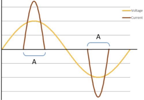
Figure 1
For the ferro UPS, the voltage-current relationship is shown in figure 2. The ferro incorporates a LC tank circuit operating in magnetic saturation, causing voltage to rise quickly to a maximum value then remain constant for a portion of each AC cycle. Segment (B) represents the portion of each AC cycle where instantaneous voltage is high enough to energize the powered equipment. Power is consumed during this period.
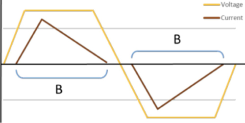
Figure 2
Because the ferro’s output voltage is above our critical threshold for a longer period within each AC cycle than its sinusoidal counterpart, current is consumed and energy provided for a longer period within each AC cycle. This results is lower peak currents for a given constant power load. Also, the ferro’s high impedance output naturally limits peak currents. Limiting peak currents results in less voltage drop across coax segments and more usable voltage further away from the ferro than would be available from an equivalent linear UPS.
Power Factor
Power factor expresses a relationship between voltage and current. In systems containing only sinusoidal voltages and currents, power factor relates to the AC phase angle difference between voltage and current and is caused by inductive or capacitive loads. The smaller this angle, the more efficient the power.
In systems containing non-sinusoidal voltages and currents such HFC networks, power factor relates to the presence and effect of harmonic currents. Loads drawing non-sinusoidal current will generate harmonic currents in addition to the fundamental AC current. The addition of unwanted harmonic currents will increase the network’s overall RMS current. Higher RMS current results in higher voltage drops across spans of powered coax.
V(drop) = I(RMS) x R(coax + passives)
Also, higher voltage drops mean less voltage is available for equipment located some distance from the power supply. If the V(in) to any network gear is below that equipment’s low voltage threshold then alternative powering must be considered.
Power Factor Correction (PFC) in HFC Networks
Power Factor Correction (PFC) circuitry is designed to reduce or eliminate any voltage-current phase difference (sinusoidal current) and harmonic currents (non-sinusoidal current) to increase power efficiency. Although PFC is common in equipment connecting to utility power, PFC has never been widely adopted in HFC networks. Implementation would be simple enough. Linear power packs within the nodes, amplifiers and virtual hubs of the network would be replaced with power packs implementing PFC. There is added cost associated with the active PFC circuitry but what are the benefits?
One often asked question is if PFC loads within the HFC network will reduce energy consumption at the ferro and reduce the associated energy bill. Not as much as you might think. The large ferro-resonant transformer acts as a passive PFC device insulating the HFC load from the AC line utility and providing an almost constant utility power factor of 0.9, irrespective of the power factor of the various HFC loads. As a result, changing HFC gears’ power supplies from linear to PFC style has little effect on utility power cost.
A second potential benefit of PFC enabled HFC loads is the reduction of harmonic currents. This would lower the RMS current and increase usable power. Lower RMS current also means less voltage drop across coax spans, increasing the network’s usable voltage reach. A trade-off for these benefits is PFC implementation efficiency. PFC circuits typically utilize an active dual conversion method for managing current. This draws more power than the traditional non-PFC linear power conversion approach and results in some efficiency loss.
To quantify the actual benefit of HFC PFC the network topology must be considered. Actual efficiency improvements and voltage reach will vary at each load and is determined by multiple factors including load current, input voltage, resistive effects of coax and passives and the efficiency of any PFC implementation.
A final word of caution. The ferro’s trapezoidal voltage and current output wave shapes change dramatically with various load profiles and are implementation specific. PFC implementations must adapt to these differences to be effective. PFC can provide benefits within the HFC network. However, considering options, there is no substitution for live network testing to assure results are as expected.

Rob Anderson
Sr. Director of Product Management
Alpha Technologies
Rob brings over 35 years of industry experience to his role at Alpha. After 10 years working as a Design Engineer in the data communications industry, Rob moved to Bellingham, WA in 1993 to join Alpha as a Sr. Design Engineer. In the 25 years since joining Alpha, Rob has held various positions in Development Engineering, Product Management and Business Development. As Senior Director of Product Management, Rob is currently responsible for all broadband powering and communications products.