DWDM is Coming to a Distributed Access Architecture Near You
By Mike Venter
VeEX Inc. (Advertorial)
The cable industry’s optical networks are undergoing rapid and radical changes to support new distributed access architectures (DAAs). A DAA basically involves replacing legacy analog infrastructure with new remote PHY devices (RPDs) or remote MAC/PHY devices (RMDs). These technologies feature a simplified design, better IP convergence, greater network efficiency and a reduction in operational costs, all key benefits to delivering a scalable and technology agnostic converged interconnect network (CIN).
DAA is having a huge impact on both the access and associated aggregation and transport networks. Delivery of high bandwidth services using a DOCSIS 3.1/R-PHY architecture requires a resilient network that will support the total capacity of all R-PHY nodes — for cable operators this involves migrating from an analog fiber distribution to a digital fiber distribution architecture based on Ethernet. Digital 10 GE optical links operate over longer distances compared to analog optical links, so the changeover to digital fiber represents several benefits to the operator. Ultimately, deeper fiber penetration is mandatory as backhaul bandwidth requirements evolve, especially as coherent optics being deployed in the metro core/backbone portion of the network are starting to be considered for high bandwidth, business applications in the access domain.
One thing remains certain, new technology variants and different deployment scenarios will greatly influence the way HFC networks are installed, tested and maintained in the future, particularly at the optical layer. While CWDM and DWDM technologies are no stranger to the industry’s networks, increased fiber availability, advances in digital fiber coupled with the cost/operational benefits of RPD/RMD will accelerate more DWDM adoption.
DWDM Testing Dilemma
Testing and maintaining DWDM networks is more complex than traditional HFC networks and can present many challenges during the installation, maintenance and troubleshooting phases if you are not equipped correctly. The plight of technicians and engineers struggling with expensive legacy WDM measurement equipment trying to verify wavelength routes or activating new customers without disrupting service has inspired a new generation of innovative DWDM test products. For example, tunable laser sources (TLS), optical time domain reflectometers (OTDRs) and optical channel checkers (OCCs) have been purpose-built to simplify DWDM testing, enabling novice and experienced users to identify, document and resolve the root causes of related performance issues and outages.
DWDM Access Networks — What to Test?
- Wavelength and Power Levels — A wavelength selective power meter better known as an OCC is perfect for scanning the channels and power levels on a MUX/D-MUX protected monitoring test point. A good OCC such as the VeEX FX180X will identify/select the correct wavelength spacing and compare the measured values against the applicable ITU-T G.694.1 grid. Missing channels including offsets exceeding predefined thresholds will flag wavelength drift or bad filtering issues. The FX180X also has the ability to display results in both tabular and graphical bar graph views with PASS/FAIL standards, which is extremely useful when performing spot checks.
- Wavelength Routing and Continuity — this can be performed using a single ended or dual ended test approach:
- Single ended — uses an OTDR which injects a pulse of light into the fiber and traces the fiber route and locates problems based on the scattering and reflections it receives. Unlike conventional models, the VeEX RXT-4111 and 4113 DWDM OTDR series can be tuned in 50 nm steps across the C-band range and are the instruments of choice to test through wavelength-specific components (MUX/D-MUX, OADM) without disrupting adjacent channels or service. They are also indispensable tools to verify wavelength routes prior to activating new customers. Fiber breaks, bad components including contaminated connectors can also be identified. In some cable networks, DWDM wavelengths may traverse a CWDM network using the 1531/1551 nm or express port on a CWDM mux. Having both DWDM and CWDM wavelength support in the RXT-4113 OTDR is particularly useful in a hybrid network. The only real technical disadvantage to using an OTDR is when active elements such as ROADMs or erbium doped fiber amplifiers (EDFA) have been implemented on the DWDM link. An isolator in these active devices blocks the OTDR’s test signal in the return direction defeating the measurement approach.
- Dual ended — A tunable DWDM laser source like the FX87 transmits a CW signal into the fiber and is used in conjunction with a FX180X OCC or FX82 optical power meter (OPM) located at the remote test point. The FX180X OCC detects the test wavelength generated by the FX87 TLS and measures its optical level. The FX82 OPM method relies on a WaveID feature to verify wavelength routing at the correct D-MUX point. In this case, the FX87 TLS transmits the desired test wavelength with a unique tag, which a VeEX compatible OPM will recognize. Besides wavelength identification, the tag also ensures the OPM sets the calibration to the proper value allowing accurate power measurement. If the TLS is fitted with standard modulation (270, 330, 1000, 2000 Hz) capability, an industry standard fiber identifier such as the VeEX FX15 can be used to identify the incoming test wavelength based on the modulation it detects. Depending on the DWDM configuration and number of fibers the customer has implemented, another approach is to perform a loopback test using a “hard” loop and a return fiber. This method requires a TLS with a high power output and embedded OPM option to perform the WaveID measurement. Despite the test approach taken, the TLS is usually a cheaper option for pure end-to-end routing applications compared to an OTDR. Another big advantage is the TLS test method is not affected by active devices which may be present on the network. See Figure 1.
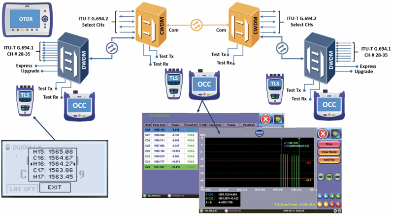
Figure 1.
- Optical Signal to Noise Ratio (OSNR) — Defined by the ITU-T G.697 Recommendation, OSNR is the ratio of optical signal power to noise power and reflects the quality of the transmitted optical signal and quality at the receiver end of the link. Traditionally, OSNR was a convenient metric for characterizing amplified optical transport systems, however new modulation formats including advanced coding and forward error correction (FEC) typical of today’s digital fiber signals have greatly improved impairment tolerance and thus OSNR measurement has become less important in short haul DWDM access deployments giving rise to optical channel checkers which typically don’t offer this measurement.
In summary, the requirement for a new generation of DWDM test equipment has arrived, and VeEX is ready to meet customer demands with leading edge solutions at an affordable price point.
For more information, visit www.veexinc.com.

 Mike Venter
Vice President, Fiber Product Development,
VeEX Inc.
Mike Venter is vice president, fiber product development, at VeEX Inc. He has been with VeEX since its inception in 2006 and is currently responsible for the company’s fiber optic product and business development worldwide. He has held several RF, microwave, and optical product engineering and management roles in the telecom market for over 35 years and fiber test and measurement since 1989.