A Closer Look at DOCSIS 3.1’s OFDM PHY Link Channel
By Ron Hranac
As announced at CES in January 2019, 10G is the cable industry’s platform to provide residential Internet speeds of 10 gigabits per second (Gbps). Those speeds will be supported by a combination of technologies, including DOCSIS® 3.1, DOCSIS 4.0, coherent optics, advanced Wi-Fi, and more. The first version of the DOCSIS 3.1 set of specifications was introduced in late 2013, and since then the cable industry has embraced DOCSIS 3.1 to deploy gigabit-class data services — part of the foundation for what’s coming in 10G — in today’s hybrid fiber/coax (HFC) networks.
DOCSIS 3.1 downstream orthogonal frequency division multiplexing (OFDM) signals support a variety of modulation orders up to 4096-QAM (optionally as high as 8192-QAM and 16384-QAM) over channel bandwidths ranging from a minimum of 24 MHz to a maximum of 192 MHz. On a spectrum analyzer the OFDM “haystack” looks somewhat like a legacy 6 MHz- or 8 MHz-wide single carrier quadrature amplitude modulation (SC-QAM) haystack, but a lot wider.
If you adjust a spectrum analyzer’s resolution bandwidth (RBW) and video filters, and tweak the averaging, it’s possible to see what looks like small spikes sticking up from the top of the OFDM haystack, similar to what’s shown in Figure 1. Those spikes are called continuous pilots, and are used for frequency and phase tracking. They are evenly distributed throughout the OFDM signal, are always on the same frequencies within the OFDM signal, and are boosted 6 dB relative to other subcarriers. There can be anywhere from 16 to 128 continuous pilots in an OFDM signal. Continuous pilots don’t carry data, but are binary phase shift keying (BPSK) modulated with a pseudo-random sequence.
(Note: What can’t be seen in Figure 1 are scattered pilots, which occur at different frequency locations in different symbols. From symbol to symbol, scattered pilots are shifted by one subcarrier position in the increasing direction of the frequency axis, so the scattered pilots visit every subcarrier location every 128 symbols. Scattered pilots also are boosted 6 dB. Scattered pilots are used in part for estimation of channel frequency response as part of the equalization process. Like the continuous pilots, scattered pilots don’t carry data but are BPSK modulated with a pseudo-random sequence.)
If you look closely at the continuous pilots visible in Figure 1, you can see what looks like a small cluster of pilots near the center of the OFDM signal. That’s where the physical layer link channel, or PHY link channel (PLC) is located.
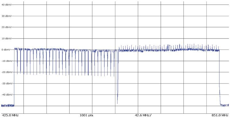
Figure 1. Spectrum analyzer screen shot showing 6 MHz-wide SC-QAM signals (left half of display) and a 192 MHz-wide OFDM signal (right half of display). The “spikes” sticking up above the top of the OFDM signal are continuous pilots.
The PLC is 400 kHz wide, uses 16-QAM for robustness, and comprises either eight or 16 subcarriers, depending on subcarrier spacing. The PLC is centered in a 6 MHz-wide “PLC band,” which contains normal data subcarriers plus a special pattern of continuous pilots. See Figure 2. The PLC band cannot have any excluded subcarriers — that is, subcarriers that have been turned off. That special pattern of continuous pilots surrounding the PLC is used by cable modems to determine where the PLC is located within the OFDM signal.
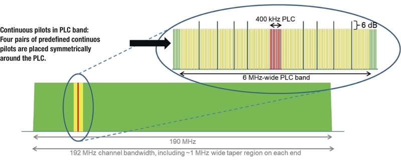
Figure 2. A graphic illustrating details in the 6 MHz-wide PLC band (yellow) and 400 kHz-wide PLC (red). Note the special pattern of eight continuous pilots surrounding the PLC. These are used by cable modems to determine where the PLC is located within the OFDM signal.
Ideally, the PLC should be placed on a frequency within the OFDM signal that is not susceptible to ingress, direct pickup, or other interference. An important point: The PLC’s frequency is user-configurable! Many operators leave the PLC set to the cable modem termination system’s default frequency, which has on occasion resulted in problems. Should the PLC be affected by ingress or other interference, DOCSIS 3.1 modems may not be able to receive and demodulate the data carried by the PLC. When that happens, those modems cannot operate in DOCSIS 3.1 mode. So, check the over-the-air environment for signals that could potentially be problematic. Don’t put the PLC in the middle of an over-the-air broadcast TV signal or LTE downlink or uplink band. That’s asking for trouble.
The PLC is a very important part of the OFDM signal, because it conveys physical layer parameters to DOCSIS 3.1 cable modems. Those parameters include the downstream profile descriptor and the OFDM channel descriptor (detailed information about each can be found in the DOCSIS 3.1 MAC and Upper Layer Protocols Interface Specification, or MULPI). Some of the specific physical layer parameters carried by the PLC include the location of the OFDM signal in the spectrum; locations of the continuous pilots; locations of excluded subcarriers; the bit loading profile (modulation order) for all subcarriers, except continuous pilots and excluded subcarriers; cyclic prefix length; roll-off setting; time interleaver depth; modulation order for the next codeword pointer; and so forth. As you can see, the PLC really does have to make it to the cable modems unimpaired.
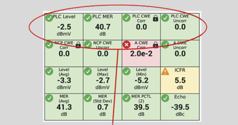
If you’re using DOCSIS 3.1-compatible field test equipment to check the OFDM signal, it’s important that the instrument be locked to the PLC. Look at the PLC’s signal level, receive modulation error ratio (RxMER), and correctable and uncorrectable codeword errors. Because of the way DOCSIS 3.1’s forward error correction works, you can generally ignore correctable codeword errors, but there shouldn’t be any uncorrectable codeword errors. Figure 3 shows an example of a field meter’s measurement of an OFDM signal in a live cable plant. This screen shot was captured in my home a year or so ago, and shows several measured metrics for a 96 MHz-wide OFDM signal, including its PLC. Of particular importance is that the PLC’s signal level is –2.5 dBmV (the level should be ≥ –15 dBmV); the PLC’s RxMER is 40.7 dB (should be ≥ 15 dB), and there are no correctable or uncorrectable codeword errors.
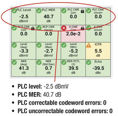
Figure 3. DOCSIS 3.1 field meter measurement of a 96 MHz-wide OFDM signal. The measured PLC parameters are in the top row.
DOCSIS 3.1 technology has enabled cable operators to provide gigabit-class data speeds in today’s HFC networks, and serves as one of the key foundational elements of the industry’s 10G platform. The downstream OFDM signal is robust and supports much higher modulation orders than we’ve used in the past. The PLC is a small but important part of the DOCSIS 3.1 downstream. Ensuring ideal placement of the PLC within the OFDM signal, along with good PLC performance metrics, will help operators provide reliable delivery of gigabit service.
 Ron Hranac
Technical Editor,
Broadband Library
rhranac@aol.com
Ron Hranac, a 48 year veteran of the cable industry, has worked on the operator and vendor side during his career. A Fellow Member of SCTE and co-founder and Associate Board Member of the organization’s Rocky Mountain Chapter, Ron was inducted into the Society’s Hall of Fame in 2010, is a co-recipient of the Chairman’s Award, an SCTE Member of the Year, and is a member of the Cable TV Pioneers Class of ’97. He received the Society’s Excellence in Standards award at Cable-Tec Expo 2016. He was recipient of the European Society for Broadband Professionals’ 2016 Tom Hall award for Outstanding Services to Broadband Engineering, and was named winner of the 2017 David Hall Award for Best Presentation. He has published hundreds of articles and papers, and has been a speaker at numerous international, national, regional, and local conferences and seminars.