A Lesson on Transmission Line Theory
By Brady Volpe
Transmission line theory can be intimidating, because of the complex mathematics involved. But I’m not going there. Transmission line theory is further complicated by modeling, say, coaxial cable (a transmission line) as a distributed circuit model, comprising series inductance, shunt capacitance, series resistance, and shunt conductance. But I’m not going there, either. Instead, I’m going to provide an analogy using a bucket of water and hose. Understanding the basic principles of transmission line theory is key to understanding how RF signals transporting DOCSIS data are impacted when problems occur at the physical layer.
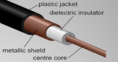
There are a couple of things you need to know: One is the definition of impedance, which is the combined opposition to current in a circuit, device, or transmission line that contains both resistance and reactance; impedance is stated in ohms. The second is that coaxial cable’s characteristic impedance is also related to the ratio of the inside diameter of the shield to the outside diameter of the center conductor, and the nature of the dielectric – specifically, the dielectric constant. Mess with any of those things, and the impedance changes!
Transmission line theory
Figure 1 shows a very simple representation of a transmission line, modeled as a source and a load. We want the impedances of the source and load to be equal to each other. If the load impedance (the resistor in the figure) is different from the source impedance, what happens? Some of the incident wave is reflected back toward the source, and the interaction of the incident and reflected waves creates standing waves! If the impedances of the source and load are equal, all of the incident wave’s power is absorbed by the load, and there is no reflection.
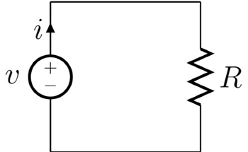
Figure 1. Simplified representation of coaxial cable
In the cable industry, all components such as amplifiers, taps, splitters and coaxial cable have a nominal impedance of 75 ohms (R = 75 ohms in Figure 1). This is by design, so please commit it to memory.
Characterizing impedance
How can we characterize the severity of impedance mismatches in a cable network? One way is with something called return loss, which is the ratio, in dB, of the power of an incident wave to the power of a wave reflected by an impedance mismatch. The higher the return loss, the less severe the impedance mismatch. So, a return loss of 30 dB is better than a return loss of 10 dB. This means we want to get the best impedance match by ensuring that everything is as close to 75 ohms impedance as possible. If the impedance of the coaxial cable is not 75 ohms or the impedances of a transmitter and receiver are not 75 ohms, then some of the incident power will be reflected. That means we will have those micro-reflections that I have mentioned which cause DOCSIS cable modems to have issues. Ah, now transmission line theory is starting to make sense.
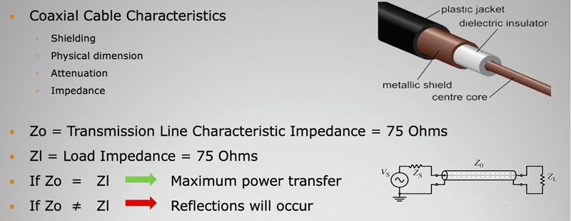
Figure 2. Coaxial cable characteristics
The analogy
Let me explain this without using math. Imagine if you have a water hose and you have a bucket of water. You want to try to pour the water from the bucket into the water hose. You tilt the bucket, and you start pouring the water into the hose. Some of the water is going to go into the hose but a lot of that water is going to splash out onto you and be “reflected” by the hose. The mismatch between the very wide opening of the bucket and very small opening of the hose can be thought of as an impedance mismatch. When we do not have a maximum power (er, water) transfer, we get wet, and this is where Brady would say, “Hey man, you have a micro-reflection; a really big micro-reflection.”
Now consider if you were to put a funnel into the opening of the hose. When you tilt the bucket into that funnel a lot more of the water is going to go into the hose and less of the water is going to be “reflected” back onto you, so you won’t get as wet. You have more transfer of water into the hose and a much more efficient system. The funnel has created an impedance match and your system is much more efficient. This would be similar to fixing a bad connector – kind of…
Impacts of micro-reflections on DOCSIS modems
Now that we have a better understanding of transmission line theory – I’m hoping you got a little wet trying the bucket and hose test at home – we can look at the practical applications. The first one is the impedance mismatch, which most often creates our micro-reflections.
The definition of a micro-reflection according to the PNM Best Practices Primer: HFC Networks (DOCSIS® 3.1) is “A short time-delay echo or reflection caused by an impedance mismatch. A micro-reflection’s time delay typically ranges from less than a symbol period to several symbol periods.” [1] Other DOCSIS specifications, particularly the DOCSIS PHY specifications, define the maximum level of micro-reflections tolerated (along with time delay), which is typically no more than -10 dBc for a single micro-reflection.
Figure 3 shows PNM data from a single cable modem having three upstream channels. Each upstream channel is experiencing an impedance mismatch as it is traversing the HFC network from the subscriber’s home to the headend. As can be seen, the highest-frequency upstream channel has the worst micro-reflection, at -10.5 dBc. As described earlier, an impedance mismatch means we do not have maximum power getting from source to load, because whatever caused the impedance mismatch resulted in some of the incident signal being reflected. That, in turn, caused standing waves, showing up as degraded in-channel frequency response (ICFR), which could be causing higher upstream transmit power.
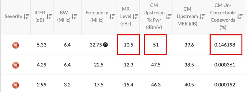
Figure 3. Impaired upstream due to an impedance mismatch causing micro-reflections
Also, worth noting in Figure 3 is that the MER is 39.6 dB. This is very good MER, and most technicians would read this on their meter and state there are no upstream issues because of such high MER. We know there are issues in the upstream because we are using PNM and not relying on just MER as a single metric to determine our pass/fail criteria. We see that although MER is good, we have micro-reflections, and we know that we have an impedance mismatch somewhere because we understand transmission line theory. Further aggravating things is the presence of a small amount of uncorrectable codeword errors. Because the MER is good, the likely cause of the codeword errors is impulse noise (adaptive pre-equalization will help compensate for the micro-reflections).
Water and DOCSIS RF signals
Back to my water hose analogies again, but this is important and pulls everything together! What if I told you water and RF signals are the same when we think of them in terms of troubleshooting? Yeah, I’m completely serious, so here goes:
Brady’s top five analogies of cable and water hoses:
- Tighten all RF connectors, just like you tighten your water hose, or else RF will leak out just like water leaks out of your water hose.
- What happens when you kink your water hose? The water slows down. The same thing happens when you kink coax because you create an impedance mismatch – so don’t over-bend cable.
- Have you ever tried cutting a water hose while it’s under pressure? It leaks. A coaxial cable will leak, too, if you nick its outer shielding – this also creates a micro-reflection (i.e., impedance mismatch).
- Did you ever drive over a water hose while it was on? Notice the pressure drop? That was because you created an impedance mismatch. If you dent a coaxial cable, you have an impedance mismatch and thus a micro-reflection. Hey, you’re still not using staples to nail up that coax on a pole or house, are you? Those create many small micro-reflections, don’t you know?
- Did you ever turn on your hose and forget to terminate the end of it? Yeah, I have, too, and got all wet until I put the spray head on. Those hose terminators sure are important. If you don’t terminate your plant you end up with a lot of impedance mismatches. Or if your terminators are burnt out due to surges that is the same as leaving the end of your hose open. You have one huge micro-reflection, dude. ☺
Wrap-up
Some of the concepts of basic transmission line theory are fairly basic and easy to understand, so don’t be intimidated. Understanding these basics will help you advance in your career. More importantly, understanding the root cause of any impairment, whether it is micro-reflections or getting wet from mismanagement of a water hose, will enable you to more effectively resolve problems correctly. Understanding core concepts, such as those discussed in this article are fundamental. This is transmission line theory 101. We must maintain 75-ohm impedance throughout our HFC network. Anything we or nature does that changes this will cause problems that must be fixed or our subscribers will be impacted.
References:
[1] PNM Best Practices Primer: HFC Networks (DOCSIS® 3.1), CM-GL-PNM-3.1-V01-200506
(Image of coax and circuit is licensed under the Creative Commons Attribution-Share Alike 3.0 Unported, 2.5 Generic, 2.0 Generic and 1.0 Generic license)
 Brady S. Volpe
brady.volpe@volpefirm.com
Brady Volpe is Founder of The Volpe Firm, Inc and Nimble This LLC. He has over 25 years of broadband cable and telecommunications industry experience specializing in RF, DOCSIS, PNM, and Internet Protocol. Mr. Volpe has been providing a wide range of troubleshooting, design solutions, services and seminars for cable operators and broadband companies specializing in DOCSIS, System Design, PNM, and Troubleshooting. He is a highly respected published speaker, both domestically and internationally. He also hosts a popular industry YouTube and Podcast – “Get Your Tech On“. Mr. Volpe has a MSEE with honors and a BSEE.