Skin Effect and Skin Depth
By Ron Hranac
Skin effect in metallic conductors is an important part of the coaxial cable portions of our networks. Skin effect ensures our radio frequency (RF) signals stay inside of the cables and other components — assuming the shielding is intact, of course. Skin effect is also a major factor in coaxial cable attenuation and is a key reason why attenuation increases as the frequency increases.
Consider an electrical conductor such as a wire carrying an electric current. For direct current (DC) applications, the entire cross section of the wire conducts the current, as shown in Figure 1.
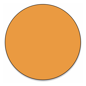
Figure 1. For DC, the entire cross section of the conductor carries the current.
For alternating current (AC) applications — which includes RF — conduction of current is largely confined to a region at and near the surface of the conductor, as shown in Figure 2. The higher the frequency, the shallower the region (and closer to the surface) in which the current is conducted. This phenomenon is known as skin effect.
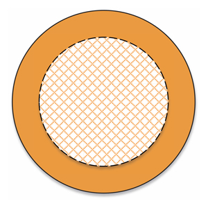
Figure 2. For AC, most of the current travels at and near the surface of the conductor.
Skin depth, denoted by the symbol δ, is a measure of skin effect and is the depth at which the current density is 1/e of the current density at the surface of the conductor. Note: “e” is the mathematical constant that is the base of the natural logarithm (“LN” on my scientific calculator) and is equal to about 2.718, so 1/e ≈ 37%. See Figure 3.
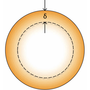
Figure 3. Skin depth δ is the depth at which the current density is approximately 37% of the value at the surface. RF current doesn’t stop at the dashed line but decreases logarithmically with respect to depth in the conductor.
Crunching the numbers
For those interested in the math to calculate skin depth, here is the formula.

where
δ is skin depth in meters
ρ is resistivity of the conductor in Ω·m (1.678*10-8 for copper at room temperature)
f is frequency in hertz
µ0 is the permittivity of free space (4π*10-7)
µr is relative permittivity of the conductor (0.999991 for copper)
If you plug in the numbers for 60 Hz in a copper conductor, the skin depth is about 0.33 inch. At 1 GHz, skin depth in copper is only 0.000081 inch. Table 1 shows values for a few other frequencies of interest.
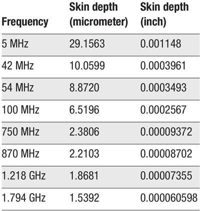
Table 1. Skin depth versus frequency for a copper conductor. 1 micrometer (µm) is 1×10⁻⁶ meter (0.000001 meter), sometimes called a micron. An on-line skin depth calculator can be found at http://chemandy.com/calculators/skin-effect-calculator.htm
But why?
Space limitations preclude an in-depth explanation of why AC travels at and near the surface of a conductor. The simple reason is that alternating current induces circulating eddy currents in the conductor, which oppose current flow deeper within the conductor. An excellent overview of this phenomena can be found at https://en.wikipedia.org/wiki/Skin_effect
How does skin effect impact attenuation?
The book Modern Cable Television Technology, 2nd Ed. includes a discussion about coaxial cable attenuation (pp 429-434). In particular, the book notes attenuation as a function of frequency is related to four factors:
- Radiation out of the cable due to imperfect shielding
- Resistive losses in the cable conductors
- Signal absorption in the dielectric
- Signal reflection due to mismatches between the cable and terminations or along the cable due to nonuniform impedance.
Looking at resistive losses in a conductor, skin effect means that the effective cross section of the conductor is less for AC because most of the current travels on and near the surface. As the frequency increases, skin depth decreases, making the effective cross section of the conductor even smaller. That, in turn, increases the “RF resistance” as the frequency increases, resulting in greater attenuation at higher frequencies compared to lower frequencies.
Figures 4 and 5 show the cross section of 0.109 inch diameter copper-clad aluminum center conductor from 0.500 hardline coax. I’ve estimated that the copper cladding is about 0.0028 inch thick. At 5 MHz the skin depth δ is about 0.0012 inch, and at 100 MHz it’s about 0.0003 inch. For both frequencies the copper cladding is more than thick enough, so no need for a solid copper center conductor. As you look at the figures, though, you can clearly see the effective cross section (pink areas) of the center conductor decreases as the frequency increases, contributing to the attenuation being greater at higher frequencies (the same thing happens with the inner surface of the shield).
Skin effect has long been one of those things we tend to take for granted, often not fully understanding what’s going on under the hood. Clearly, though, skin effect and skin depth are important parts of the way our cable networks operate.
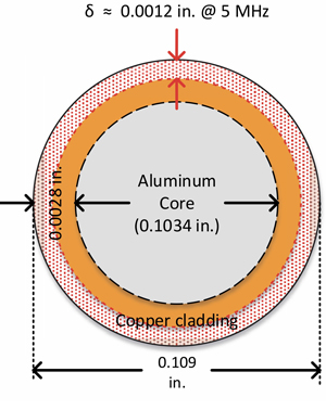
Figure 4. The skin depth at 5 MHz is about 0.0012 inch; the conductor’s effective cross section at this frequency is shown in pink (illustration not to scale).
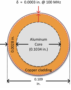
Figure 5. The skin depth at 100 MHz is about 0.0003 inch, making the conductor’s effective cross section significantly less than it is at 5 MHz (illustration not to scale).
 Ron Hranac
Technical Marketing Engineer,
Cisco Systems
rhranacj@cisco.com
Ron Hranac, a 47 year veteran of the cable industry, is Technical Marketing Engineer for Cisco’s Cable Access Business Unit. A Fellow Member of SCTE and co-founder and Associate Board Member of the organization’s Rocky Mountain Chapter, Ron was inducted into the Society’s Hall of Fame in 2010, is a co-recipient of the Chairman’s Award, an SCTE Member of the Year, and is a member of the Cable TV Pioneers Class of ’97. He received the Society’s Excellence in Standards award at Cable-Tec Expo 2016. He was recipient of the European Society for Broadband Professionals’ 2016 Tom Hall award for Outstanding Services to Broadband Engineering, and was named winner of the 2017 David Hall Award for Best Presentation. He has published hundreds of articles and papers, and has been a speaker at numerous international, national, regional, and local conferences and seminars.


