Persistent Myths and Bad Habits
Ours is an industry that has its own technology-related myths and good ol’ bad habits. I’m certainly guilty of some of those bad habits, especially earlier in my career. Here are a few of my favorites, which, unfortunately, probably will always be with us.
Mysterious static or capacitance buildup
This is a myth that seemingly never goes away. I first wrote about the supposed static or capacitance buildup in the January 2008 issue of Communications Technology magazine. Here are the first couple of paragraphs from that article:
“How many times have you or someone you work with visited a subscriber’s home in response to a service call about snowy pictures on some of the analog channels, and perhaps problems with some of the digital channels? The drop is disconnected from the ground block or splitter on the side of the home and connected to a signal level meter (SLM) or other instrument. Signal levels are fine, so the drop cable is reconnected. Amazingly, the snowy pictures are snowy no more, and any digital problems stopped being problems. What the heck is going on here?
“One explanation that has been the subject of lengthy discussions on the SCTE-List and elsewhere is the so-called capacitance effect. Disconnecting the drop and hooking it up to the test equipment somehow discharged a static or other mysterious charge buildup in the drop cable, solving the problem! Bunk.”
I went on to explain the chemistry of corrosion on the center conductor, which is the real cause. That corrosion, which may anywhere from less than a micron to perhaps a few microns thick, acts like an insulator or attenuator. The action of disconnecting the drop from, say, the ground block, and connecting it to a meter, scrubs some of the corrosion, exposing fresh copper and restoring signal levels to what they’re supposed to be. An archived copy of the CT article can be found on SCTE’s website here: https://tinyurl.com/9ud9wjvu
Coax attenuation vs temperature
Most of us are familiar with the attenuation of coaxial cable versus frequency: The attenuation through a length of coaxial cable is greater at higher frequencies than it is at lower frequencies. For instance, the typical attenuation of 100 feet of Series 6 drop cable at 1 GHz is 6.55 dB, and at 55 MHz is only 1.6 dB.
Coaxial cable attenuation is affected by temperature, too. Cable attenuation in decibels changes about 1% for every 10 °F ambient temperature change. As the temperature increases, cable attenuation increases; as the temperature decreases, cable attenuation decreases.
Some mistakenly believe the attenuation versus temperature variation is related to the cable’s expansion and contraction. As the cable expands, or gets longer when the weather is warm, that might explain why the attenuation increases. There’s more loss because there is more cable for the signal to go through. Cold weather means less attenuation because the cable contracts, or gets shorter. While coaxial cable does expand and contract over temperature, the length change isn’t enough to explain the attenuation variation. I originally wrote an article about this for Communications Technology back in April of 2002. In a nutshell, the cause of coaxial cable’s attenuation variation over temperature is related to processes occurring at the atomic level. You can read the content from that article on SCTE’s Rocky Mountain Chapter website here: https://tinyurl.com/ycyvk6rt
Where did that water come from?
Most techs who work in the outside plant have run across an active device that has or had water in it. I’ve occasionally heard some say the problem is poor device quality, but that is rarely the real reason. Aside from the obvious causes (e.g., improper or missing weatherproofing on connectors, missing port plugs or caps, lid left loose or open, etc.), one not-so-obvious culprit is a warped housing and/or lid. Housing or lid damage typically happens when the closure hardware is incorrectly tightened. Active device manufacturers have for decades provided tightening torque values and tightening sequences when closing and securing amplifiers or nodes. From what I’ve seen in the field, those guidelines are rarely followed.
Figure 1, from the installation manual for a Cisco 1.2 GHz GainMaker® System Amplifier, shows the tightening sequence for that device’s housing. According to the manual (available online), the following steps are supposed to be followed.
- Make sure that the housing gaskets are clean and in the correct position. Wipe off any excess dirt and debris.
- Close the housing. CAUTION: Ensure that all the cables are out of the way when closing the housing.
- Lightly secure the six ½-inch closure bolts with a hex driver or ratchet.
- Using a torque wrench, tighten the six closure bolts to 25 lb-in (2.8 N m).
- Important: Tighten the closure bolts in the correct sequence as specified in Torquing Sequence (on page 42).
- Using the same pattern, tighten the housing closure bolts from 5 lb-ft to 12 lb-ft (6.8 N m to 16.3 N m).
Bottom line? Check with the manufacturer of actives used in your cable network for housing closure procedures. It really is important to follow those guidelines.
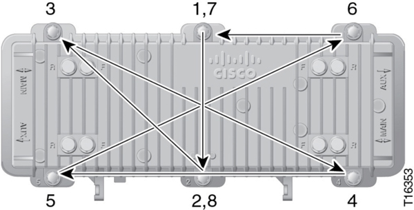
Figure 1. Bolt tightening sequence for a GainMaker System Amplifier housing.
Graphic courtesy of Cisco
EIA channels vs CTA channels
This one falls in the “old habits die hard” category. The use of 6 MHz-wide cable channels and their numbering are defined in the Consumer Technology Association Standard CTA-542-D S-2023 (“Cable Television Channel Identification Plan”). In years past, the channel designations were variously known as IS-6, NCTA, NCTA/EIA, EIA, EIA/CEA, and CEA channels, but today are CTA channels. Some still call the 6 MHz-wide channels in cable networks “EIA channels,” but that designation was deprecated more than 20 years ago, replaced at the time with “CEA channels.” When the Consumer Electronics Association changed its name to Consumer Technology Association, the standard’s name changed, as did the channel designation. Repeat after me: “CTA channels.”
That leakage is really strong
I can’t tell you how many times I’ve seen online posts with photos or videos showing a leakage detector held just inches from a leak, with the detector reporting 2000 microvolts per meter (µV/m) or greater. Unfortunately, that measurement is bogus. In order to get an accurate signal leakage field strength reading, the detector and its antenna must be in what is called the far-field region of the leakage source. Figure 2 shows a dual-band detector close to a leakage source. The detector is in the far-field for the higher frequency leak (450 µV/m), but is in the near-field for the low frequency leak (2100 µV/m). The former is a good value, but the latter is not. Moving the detector farther from the leakage source will improve the accuracy of the low frequency field strength measurement.
You can find more about calculating the near-field and far-field boundary for a half-wave dipole antenna in Section 19.2 of the operational practice SCTE 270 2021r1 Mathematics of Cable, available on SCTE’s standards download page at https://tinyurl.com/4kh4z4yk
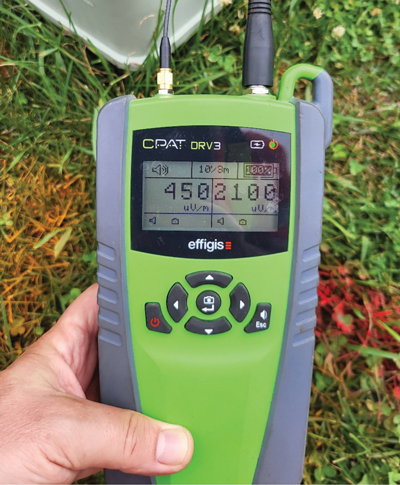
Figure 2. Dual frequency leakage measurement.
Photo courtesy of Arni Lundale
Got FECs?
Forward error correction (FEC) is a means of compensating for errors during data transmission. From a high level perspective, redundant data is sent along with the payload, allowing the receiver to detect and correct certain errors. FEC often can be described as layers of techniques that together help make data transmission more robust. For instance, FEC encoding used with downstream ITU-T J.83-based SC-QAM channels includes a combination of Reed Solomon encoding, interleaving, randomization, and Trellis encoding.
When errors can’t be fixed in the receiver, we get uncorrectable codeword errors, which means packet loss. Some call codeword errors FEC errors, but too many simply call them FECs. Remember, forward error correction is a core part of data transmission, so there is always FEC. Figure 3 shows an example of correctable codeword errors (a.k.a. correctable FEC errors or just FEC errors) in an OFDM channel. Those errors, whether correctable or uncorrectable, are not FECs.
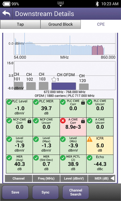
Figure 3. Correctable codeword errors in an OFDM channel. It’s okay to call these FEC errors, but they are not FECs.
Wrapping up
There are many more myths and bad habits than I can cover here. Because ours is a technology-based industry, I think it’s important to be technically accurate to the extent possible, especially to avoid misunderstanding or confusion. Some age-old myths and bad habits are not harmful, but others can be. An example of the latter is active device housing damage caused by improper tightening of closure hardware. It all boils down to being the best at what we do.
Images provided by author, Shutterstock.
 Ron Hranac
Technical Editor,
Broadband Library
rhranac@aol.com
Ron Hranac, a 52 year veteran of the cable industry, has worked on the operator and vendor side during his career. A Fellow Member of SCTE and co-founder and Assistant Board Member of the organization’s Rocky Mountain Chapter, Ron was inducted into the Society’s Hall of Fame in 2010, is a co-recipient of the Chairman’s Award, an SCTE Member of the Year, and is a member of the Cable TV Pioneers Class of ’97. He received the Society’s Excellence in Standards award at Cable-Tec Expo 2016. He was recipient of the European Society for Broadband Professionals’ 2016 Tom Hall Award for Outstanding Services to Broadband Engineering, and was named winner of the 2017 David Hall Award for Best Presentation. He has published hundreds of articles and papers, and has been a speaker at numerous international, national, regional, and local conferences and seminars.