Fiber Deep Dive with a Network Designer
By Teresa Bazzle
What happens when a FTTH designer switches gears and designs for node+0 networks? This article explores the different considerations fiber deep network design requires, and how fiber deep and PON networks are complementary.
Front of mind for cable operators today are ever-increasing customer bandwidth needs, particularly related to service expectations and preparing for the future. Getting ahead of demand entails driving digital-to-RF transition away from the headend — deeper into the network — and planning now for co-existence with additional technologies. Much of the focus has been on transforming traditional hybrid fiber-coaxial networks to fiber deep networks. But it could be that a passive optical network (PON) for tomorrow may become an integral part of the fiber deep planning process beginning today. With that being said, how does someone with a strong background in PON FTTx design approach a fiber deep network design?
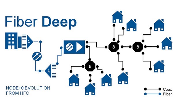
Make no mistake — there are differences between fiber deep and PON architectures. In a fiber deep or node+0 architecture, no active devices are used except for the fiber node. In this unamplified architecture, a large serving area currently served by one analog node is broken into smaller areas each serving around 64 to 128 subscribers, using fiber-fed “child” nodes. This configuration brings the optical-to-electrical conversion much closer to the subscribers, simplifies the network operation by eliminating powered amplifiers, and increases the bandwidth capability.
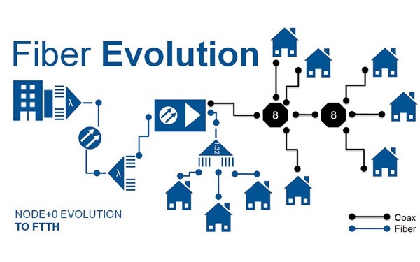
A FTTH or PON scenario takes the fiber even deeper into the network. An optical line terminal (OLT) typically serving thousands of homes replaces the functions of the parent and child nodes. The OLT provides signal to many passive optical splitter inputs. Each splitter breaks the signal into 16, 32, 64, or 128 outputs, each carrying the same signal. An optical fiber then is used all the way to each home or business. At the house, an optical network terminal (ONT) converts the signal back to electrical for distribution over present-day in-home connectivity platforms.
Let’s explore the main components of the network updated by a fiber deep-to-PON transition from the subscriber to the headend. From the home to the curb, a single-fiber drop replaces the coax drop. One fiber is usually enough, since the technology supports multiple wavelengths transmitted over a single fiber. Drop cables can be factory connectorized with environmentally hardened connectors on one end or on both ends, providing flexibility for the installer. Field-installable connectors can also be used. The drop may connect to a network interface device (NID) housing to create an interface between the outside and inside of the house, where an indoor fiber drop assembly can be used to connect to the ONT.
In the neighborhood, optical fiber replaces hardline coax cable, multiport optical terminals replace taps, and environmentally hardened single-fiber and multifiber connectors replace RF connectors. These products are specifically designed to increase deployment speed and network capability with reduced installation disruptions. In a typical design, a multiport would be connected or spliced to the distribution fiber in the cable and act as the transition from the drop to the home.
The distribution cable may be a bulk cable or can be factory terminated with specific multifiber access points for additional ease of installation. In bulk cable applications, both loose tube and ribbon cable serve the distribution plant well, and modern versions streamline cable access procedures as well as the fiber splicing process through advancements in jacket access technologies and ribbon splicing efficiencies.
These cables may then meet at a splitter cabinet or housing, which contains the designed quantity of splitters of the predetermined split ratio, typically anywhere from 1×16 to 1×64. From this housing, feeder fibers connect the splitter inputs to the OLT. Feeder fibers may be loose tube or ribbon cables, and can be high-fiber-count cables and/or part of a fiber cable ring topology.
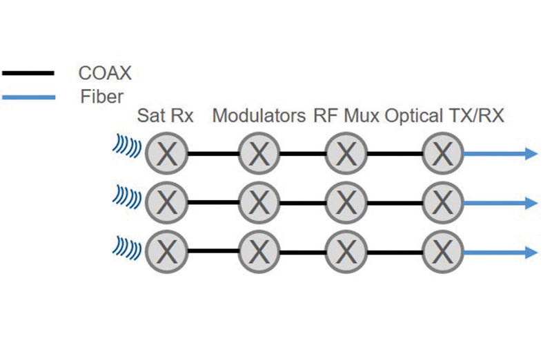
In the headend, the influx of new technologies may introduce a combination of passive optical splitters, dense wavelength division multiplexing (WDM) devices, gigabit ethernet switches, and machine virtualization. Headend transformation may require planning for more dense, modular fiber optic hardware that can support multiple activities in a limited footprint. And to maintain flexibility between these services, the passive hardware may need to be configured using a cross-connect methodology instead of interconnect.
When designing a PON-ready fiber deep network, adopting four mantras can streamline the migration:
Size distribution areas based on standard PON split ratios
Coax design has been based on the same counts as served by the standard PON split ratios (32, 64, 128, 256 — all multiples of 8), which means that a designer will have a good feel for the size of the distribution area (DA) to be served. However, standard FTTx products typically use multiples of 12 fibers. Although not an exact match for the splitters, it can be beneficial as it provides for “built-in” overprovisioning. For example, a standard neighborhood of 128 homes could be served with a passive splitter terminal or cabinet sized at 144 fibers. The extra 16 SC APC ports in the cabinet could support spare ports in the field or fibers bypassing the splitter. Also, products designed in 12-fiber units make splicing less complicated for installers.
Optimize the location of the child node and its associated fibers
Most HFC networks place the node central to the DA whenever possible. This design gives cable operators the ability to better balance the coax cables coming from the node. It is also a good practice (when possible) for FTTx networks. Having the fibers feeding the node drop at the same location as a future splitter cabinet will make the transition easier. You might also consider what type of storage might be needed for a future splitter terminal, whether that is a vault or pedestal, and ensure the proper right-of-way for that product when planning for the child note placement. Alternatively, innovations in local convergence point enclosures (LCPE) have achieved size advantages that enable colocation with child nodes. Easily deployed in vaults or on strands, LCPEs reduce the permitting and civils costs associated with traditional cabinets.
Also, if it has been determined which electronics supporting FTTx would be used to serve the neighborhood, then the number of fibers to serve both the child node and the FTTx splitters could be determined. If necessary, spare fiber could be allocated in the node cable that would either serve remote PON electronics or serve the passive optical splitters directly.
Remember that in an FTTx network, each access point is the same
Coax cable designs use a cascaded tap design and utilize diminishing/amplified power levels at each tap. This design is not a requirement in FTTx applications, as the power level at each access point is not part of the design criteria. Almost any product placement scheme can work, as long as the end-to-end system loss budget is not exceeded at any point. For example, a coax network may require multiple cables along the same path to provide enough power to service an area, but this requirement may not apply in a fiber network, as the fiber count of the cable can be sized as needed.
Ready your headend to support the gigabit era
As you bring more services into the headend, the high-value rack and floor space can be taken up quickly. Planning fiber optic hardware with usable high density can help alleviate some of these space concerns. The configuration of this hardware can also help support use in tight spaces. For example, prestubbed fiber optic housings, or housings that support fusion splicing and provide access from the front, can allow the racks to be placed against a wall, eliminating the need for access space behind the rack.
Designing your fiber deep network with an eye to the future can save costs and ease the transition to FTTx. Many companies, including Corning, provide FTTx design training and support services to help designers learn what an all-fiber network looks like and how it is designed.


Teresa Bazzle
Senior Systems Engineer,
Corning Optical Communications
Teresa Bazzle is a senior systems engineer at Corning Optical Communications. With more than 30 years of experience in fiber optics, she has focused the past 12 years on designing FTTx networks.


