Extended Spectrum DOCSIS Out of the Lab and Into the Wild
By Alan Skinner –
This article is a summary of a paper that the author co-wrote for SCTE TechExpo24, entitled “Real World HFC Plant Migration to 1.8 GHz.”
With the release of the DOCSIS 4.0 specifications, cable operators are now able to push the envelope of their HFC networks to utilize more spectrum than ever before. With extended spectrum DOCSIS (ESD, also called DOCSIS 4.0 frequency division duplexing, or FDD), providers like Cox will be operating OFDM channels all the way to 1.8 GHz—nearly doubling the spectrum in use today. And while the additional frequencies should provide a corresponding increase in available subscriber throughput—up to 10 Gbps and beyond—the gains up until this point have been either theoretical or proven only in a controlled environment like a lab.
At Cox we decided to put this new technology to the test on some of our real-world plant.
Predicted performance
At the onset of DOCSIS 4.0 spec development, Cox wanted to understand the performance that a network based on DOCSIS 4.0 FDD/ESD technology might be expected to achieve in our HFC plant. We developed a model to allow us to characterize that performance, allowing us to estimate the impacts that various factors might have, such as downstream amplifier cascade depth, amount of RF step-down in the extended spectrum, and amplifier RF output tilt.
Testing limitations
With 1.8 GHz-capable amplifiers and taps commercially available, we wanted to validate the expectations provided by our model. While Cox had built test nodes up to N+6 cascades, these nodes were based upon new construction and leveraged new cable, connectors, power supplies, etc. With these nodes being new build, we were assured that all the connections were tight and new cable met manufacturer specs. A live production node, however, offers real-world artifacts that cannot be easily replicated in a newly constructed test node. Such things as aged cable and connectors that have suffered the effects of temperature, weather, and physical damage do not enter into the performance picture for a newly constructed node. However, we did not have access to a production-ready D4.0 CMTS or cable modem so engineering prototypes were used instead. The early CMTS/node sample was very limited in its configuration options and was not hardened for outdoor use, nor was it capable of offering all the services our subscribers expect; thus, we were able to use it only for a limited time during a maintenance window.
Field test
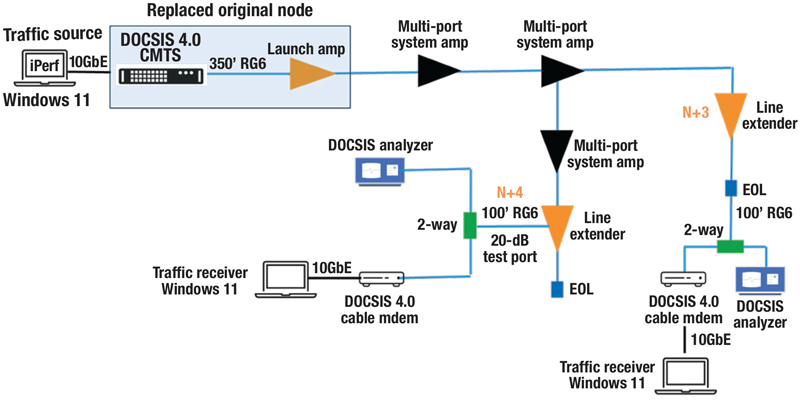
For our trial, we selected a 20+ year old node from our Phoenix market. This node was considered representative of a typical Cox N+4 node and was thought to have endured more stressful environmental conditions than an average node due to extreme temperatures in our Phoenix location. About a week prior to the field test maintenance window, the entire node was upgraded with drop-in replacement 1.8 GHz amplifiers (running in 1 GHz mode), taps and passives. While testing, the original node outputs were disconnected, and an equivalent 1.8 GHz “node” was used in its place (see Figure. 1). The equivalent 1.8 GHz node included our prototype CMTS as well as an additional line extender to provide the launch signal levels that matched the original node.

Figure 1. Production node modified for testing.

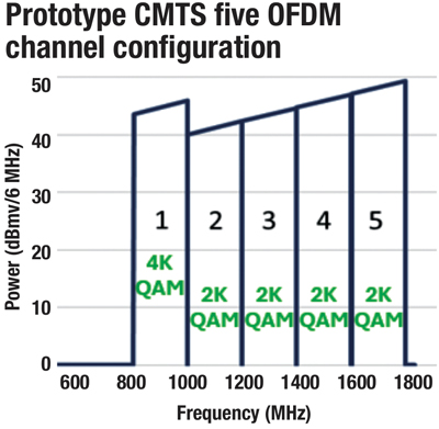
Figure 2. OFDM channel placement and modulation order.
The specific steps executed during the maintenance window test were as follows:
- Disconnect the production node and connect the prototype CMTS/node and launch amp in its place.
- Configure the CMTS for 1.8 GHz with legacy RF levels below 1 GHz and a 6 dB step-down above.
- Reconfigure each amplifier with the 1.8 GHz profile and auto-align the forward and return.
- Perform signal quality measurements and throughput testing.
- Disconnect the prototype CMTS and launch amplifier and reconnect the production node.
- Reconfigure and realign each amplifier back to the original 1.0 GHz profile.
Results—signal quality and modulation order
Configuration options supported by the prototype CMTS limited our testing to five downstream OFDM channels. Since performance was well understood for DOCSIS 3.1 signals below 1 GHz, the configuration used in the test (see Figure 2) allocated those five OFDM channels to spectrum from 808 MHz to 1768 MHz.
A primary goal of the test was to quantify the cable modem downstream signal quality using RxMER (receive modulation error ratio) measurements and compare that performance against model predictions. Cox design plans call for targeting 4096-QAM for OFDM channels below 1 GHz and 2048-QAM for OFDM channels above 1 GHz. Any performance beyond those expectations would provide further margin for our deployments.
Measurements were taken using a DOCSIS signal analyzer and our D4.0 cable modem, at the end of both the N+3 and N+4 cascades. With only one exception of -0.3 dB, every channel at both locations provided RxMER that exceeded what was predicted by the model. In fact, our testing showed that we could have increased the modulation order for channels 2-5 to 4k-QAM in the N+3 cascade, and two additional channels in the N+4 cascade as well. Regardless, we observed significant margin on each channel that should allow us to reliably and consistently run 4k-QAM below 1 GHz and at least 2k-QAM above 1 GHz for cascades up to N+4.
Results—cable modem throughput and network capacity
In order to confirm that these RxMER measurements translated into real-world modem performance, we needed to perform throughput testing over the cascade. Our testing focused exclusively on downstream throughput for a number of reasons, primarily the limitation of the CMTS upstream configuration and diplexer mismatches with the amps. With no visibility into upstream performance and no way to either diagnose or troubleshoot any upstream issues, we decided to use downstream UDP traffic to test. We expected to achieve 8.1 Gbps of throughput given our channel configuration.
In addition to being limited to downstream testing, the nature of our field test limited us in other ways. DOCSIS throughput testing is typically performed with a traffic generator wired to both the CMTS and the CM in a closed loop. Since these devices were over 1500 meters apart, we had to use a client-server-based approach. Iperf was selected to initiate UDP downstream traffic with no dependency on the upstream.
Our throughput test setup consisted of a Windows 11 computer with a Thunderbolt 10 GbE dongle connected to the CMTS over Cat8 twisted pair and used to generate just over 9 Gbps. On the cable modem side, another Windows 11 laptop with the same dongle and cable was used to measure the received traffic (see Figure 3). We were able to consistently receive between 8.0 and 8.2 Gbps through the modem using only five OFDM channels and no SC-QAM channels.
Extrapolation and next steps
As mentioned previously, our test CMTS was only able to provide OFDM channels so the throughput we achieved was not fully indicative of what the network could have provided. Given that we would also bond 32 SC-QAM channels with a fixed 1.2 Gbps of capacity were this production hardware, the actual single-modem throughput would be approximately 9.3 Gbps.
In addition, at the service group level, we expect to offer a sixth OFDM channel, operating below 1 GHz and thus consistently running 4k-QAM. With this extra channel, and with SC-QAM channels present, we fully expect to provide at least 10.7 Gbps of total service group capacity.
So, how common do we expect these results to be across a range of service group sizes and cascade depths? At Cox, over 60% of our nodes are N+4 or smaller and would expect to see the results just described. And based on the margins we observed and the modeling we’ve done, 2k-QAM above 1 GHz should be achievable out to N+6. At that point we would have covered approximately 93% of our footprint.
We look forward to additional field testing in 2025 using production CMTS/node hardware and longer cascades, but with the results of this field trial we feel confident in the direction we’re going with ESD and should be able to enjoy generous network capacity and competitive subscriber tiers for years to come.

Figure 3. Data throughput test setup.

Alan Skinner
Principal Engineer
Cox Communications, Inc.
Alan Skinner is an 18-year veteran of Cable Access Engineering at Cox Communications, where he spends his time designing and testing virtual CMTS and related DOCSIS 4.0 technologies. Prior to joining Cox, Alan spent eight years in DOCSIS engineering at CommScope and Cisco.
Images provided by author


