
A Closer Look at Routing
By Patrick Hunter —
From the time that I started the transition from field operations to network engineering, I heard lots of discussion about “routing protocols.” Even as I began to learn all about IP networks, routing, and switching, routing protocols and what they really do remained a mystery to me. Much of that was due to the fact that my responsibilities as a new network engineer were centered on simple Layer 2 devices called switches, which traditionally don’t really do any routing at all.
At this point, if you are a little fuzzy on what the difference is between routing and switching, you might want to check out the Fall 2017 issue of Broadband Libraryat broadbandlibrary.com, in which my column covered some networking basics, including the different layers of the Open Systems Interconnection (OSI) reference model. In brief, routers receive Ethernet frames via a Layer 1 (physical) connection and “open” or de-encapsulate the MAC layer information (Layer 2) in order to look at the IP addresses (Layer 3) and determine the best direction to route or “packet switch” the IP packet. So the router opens the envelope and examines the addressing on the next envelope inside. This contrasts the role of a switch, which simply receives the piece of data on a physical interface, examines the MAC information and switches the Ethernet frame out to the appropriate interface or interfaces, never taking the time to examine any information further in the envelope. (Obviously, there are exceptions to this hard and fast rule, but in theory, switches operate at OSI Layer 2 and routers operate at OSI Layer 3.)
So, at their simplest level, routers have the job of looking at destination IP address information and making sure to send the packet in the best direction. Notice that I didn’t say that they send them in the “right” direction? That’s because, as you likely know, there are often many paths to a destination in the Internet world. So, the router doesn’t just send the packet, but it actually makes decisions on a regular basis about which is the best direction possible, based on the information that the router has at the time. It is very important to note that if a router does not have any information about which direction to send a packet, it will not forward the packet. It simply cannot. The question is, from where does that information come?
It turns out that there are typically three possible sources of information for the router to use for its routing information base (RIB), commonly known as a “routing table”: the router itself, a network administrator, or other routers.
The first is the router itself. As long as there is a routing process running in the router’s “brain”, it will first identify any networks that it knows are directly connected. How would a router know which networks are directly connected, you ask? By looking at any active interfaces with an IP address configured on itself, the router can determine the networks which are directly attached or connected. If you recall, every configured IP address always has a network mask associated with it, which is the piece used to determine the size of the network. So, if the router has the IP address and the network mask, it knows the definition of the whole network attached to it. In that sense, the router actually “participates” in that particular network. (We like to say that it has an interface “in” that network.) It could be two IP addresses large, or 16, or even hundreds of addresses in size, or more correctly, “scope.” But most important is that just by having an active interface with a valid IP address and network mask, that router knows that a particular network is directly attached to it! Quite a self-informed piece of equipment, no?
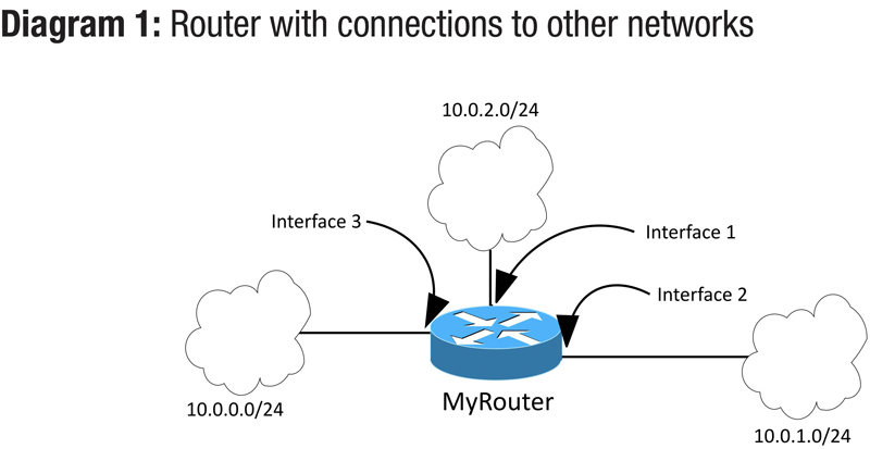
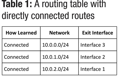
So, let’s say that a router has three active interfaces in three different networks. Its routing table would automatically be populated with the networks that live there. Each entry in the routing table reflects the network including its size, and the next hop or exit interface. That second piece is key because that’s the direction part of the decision that the router makes. Table 1 shows an example of what a routing table might look like in this case. The device, named MyRouter, has three interfaces on it, as shown in Diagram 1. It also has connections to three different networks. We have no idea what’s beyond those networks, if anything, we just know that those networks are connected to MyRouter. The image represents the three different networks as clouds to make it easy. (Network admins love to use clouds to represent things we don’t want to define explicitly.) In this case, the cloud could represent lots of switches and computers or servers, we don’t know for certain, and actually don’t need to worry about it in this context. Diagram 1 and Table 1 show how a router stores its knowledge of various networks attached to it.
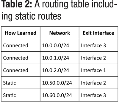
The second source of data for the routing table is a network administrator. A human can tell the router exactly which way to route packets based on that person’s decisions. This is not terribly uncommon in very small networks. Whether or not the network administrator really knows that the best path to get to other networks is through a particular interface, the router will happily send the packets that direction, no questions asked, assuming that there is an active connection on the router’s interface. The entries in the routing table that have been configured by a network administrator are commonly known as “static” routes. The next routing table example (see Table 2) shows some static routes that have been configured by a network administrator in addition to our already-known directly connected routes.
It is obvious that since there are only three interfaces on MyRouter, the path to the 10.50.0.0 network is assumed to be through the 10.0.1.0 network. Otherwise, why would the network administrator assign the exit interface to be Interface 2? It is possible that the 10.50.0.0 network does in fact live past the 10.0.1.0 network, we just can’t tell from this diagram. But, this does beg two big questions in my mind. First, what happens when an administrator configures a static route that would send the packet in the wrong direction? The answer is generally that the packets destined for that network will likely never make it there and eventually time out. (Remember our discussion about the time to live (TTL) value in IP packets from the last issue of Broadband Library?) Secondly, what happens when a network administrator configures a static route for an already known directly-connected network, like 10.0.0.0, for example? Hmmm…the router must then make a decision about which path to trust more. This is where the concept of “best direction” is tested. It turns out, that under normal circumstances, the router trusts its inherent knowledge of the directly connected network even more than the network administrator’s knowledge.
The third source of data for the routing table is other routers. By communicating with each other, different routers, with different knowledge of networks, whether they are directly connected or not, can learn about other networks dynamically. That is the precise function of routing protocols! Here is the good stuff.
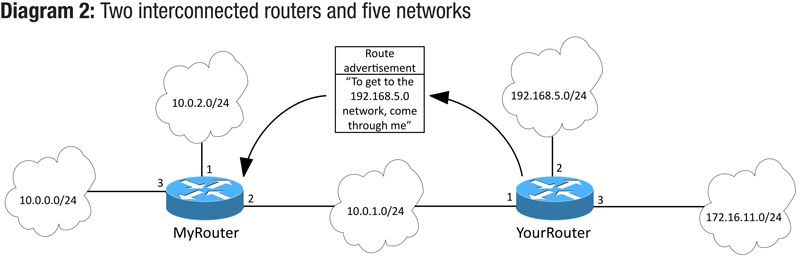
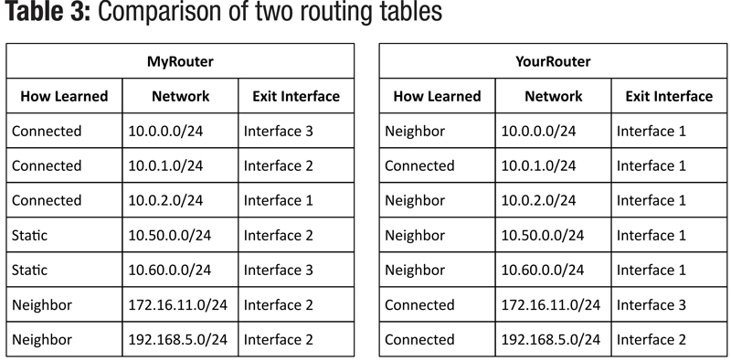
There are a couple of different general flavors of routing protocols. Most often, they are broken down into two major categories: distance vector routing protocols and link state routing protocols. They have pretty fancy names and actually are pretty darn sophisticated to tell you the truth. Both protocols have quite a few things in common. Most importantly, all routing protocols (which are just a set of rules, remember) require that two routers establish an “adjacency” or some form of neighborship. Both routers should agree on what protocol they are using, how long to wait between sending updates, and a host of other things. Once adjacencies are established, the routers essentially have agreed to share what they know with each other. If MyRouter were able to establish an adjacency with another router, say for example, YourRouter, then each of them would share the contents of their routing tables with one another.
So, for the sake of carrying the example further, let’s look at the network topology in Diagram 2. Notice that MyRouter and YourRouter are directly connected to each other and that each has other networks directly connected as well. The routing tables of both routers show clearly that they know about their directly connected networks, any static routes that must have been configured by an administrator, and the networks that their adjacent neighbor has shared with them. This is the cool part! You can see that MyRouter knows that to get to the 192.168.5.0 network, it must go through Interface 2. No network administrator had to configure static routes to allow that traffic to flow, and if for some reason YourRouter’s connection to the 192.168.5.0 network goes down or is disconnected, YourRouter will automatically send an update to MyRouter so that MyRouter can remove the entry in the routing table for that network.
This is where the magic happens in routing protocols. When a network is so large that manually configuring static routes every time there is a change, the task is beyond daunting, it’s darn near impossible. Dynamic routing protocols take care of all the work for us thankfully.
I’ll briefly touch on the differences between distance vector and link state protocols since we’ve already mentioned them here. Distance vector protocols generally pay attention only to the information that is received from a directly adjacent neighbor. They don’t give as much credence to how many routers away a particular network lives or how their neighbor learned about a network (unless it was from a whole different routing protocol). They just know that their trusted neighbor has told them that a packet can reach a particular network through the trusted neighbor and it’s some distance away, and well…that’s good enough for this router. That pretty much explains why these are called distance vector protocols: they just care about how far away a network lives and in which direction.
Link state protocols operate a little differently. Instead, each router in a link state domain attempts to build a complete map of the entire network, using the information learned from its neighbors. It does pay attention to how many routers a packet must go through and calculates the shortest path as defined by whatever routing metrics it is designed to use. Those could be hop count, bandwidth, delay, or tons of other measureable items. Based on the algorithm for determining the shortest path, the router installs the network in the routing table pointed toward the exit interface headed for that shortest path. This also explains why link state protocols are named as such. They care about the state of every link between the routers in the entire routing domain to help make a decision about the best path.
As you can see, routing protocols can be complex but they certainly provide an incredibly powerful ability to build and maintain a network. Without them, the Internet as we know it couldn’t possibly exist. There are literally hundreds of thousands of networks in the Internet routing table today, and routing protocols make it possible for the innumerable packets to reach their intended network destinations quickly and efficiently; for a network lover like me, a remarkable feat of human engineering!
 Patrick Hunter — “Hunter”
Director,
IT Enterprise Network and Telecom,
Charter Communications
hunter.hunter@charter.com
Hunter has been employed with Charter since 2000 and has held numerous positions, from Installer, System Technician, Technical Operations management, Sales Engineer, and Network Engineer. His responsibilities include providing IP connectivity and network security to all users in Charter’s approximately 1,000 facilities, including executive and regional offices, technical centers, call centers, headends, hubsites, and data centers. Mr. Hunter has served on the Gateway Chapter Board of Directors since 2005. He spends his spare time mentoring, teaching, and speaking on IP and Ethernet networks as well as careers in the network field.