
Electrical Transmission of 10G
By Patrick Hunter
In our quest for network supremacy, the cable industry has spent at least the last year talking about 10G service. We know that the future holds a great deal of promise for our service, and achieving 10 gigabits per second (Gbps) symmetrical service for our cable modem subscribers will continue to position our network solution to be the frontrunner for years to come.
In thinking about that 10 Gbps cable modem service, network engineers are taken back to those years when 10 Gbps Ethernet connectivity was first introduced to the network marketplace, and the technical hurdles that were overcome to make it possible. Like many of the advances in the network universe over the last couple of decades, making it to 10 Gbps was accomplished due to the efforts of many different sectors of the technical community, including chip and hardware manufacturers, scientists, researchers, and more. The continuous collaboration among industry participants yields amazing new capabilities every year. The physical, electrical, and optical characteristics of today’s 10 Gbps implementations are worth a deeper look. In this installment of IP Address, we’ll dive deep into the Institute of Electrical and Electronics Engineers (IEEE) 802.3 Ethernet standard, specifically focused on the 10GBASE-T sections, for 10 Gbps over balanced twisted pair copper cabling.
The latest version of the 802.3 standard is available for viewing on the IEEE Xplore website at https://ieeexplore.ieee.org. The 802.3-2018 version is the result of decades of work and currently runs about 5,600 pages! Section Four specifically addresses 10 Gbps operation and is over 500 pages in length. Let’s jump in.
Classically, discussion around Ethernet focuses on the data link component and the physical component, which map nicely to the open systems interconnection (OSI) models Layers 1 and 2. Therefore, one focuses on software and hardware/media implementations. But, for the folks at IEEE, the details of those two implementations are far more complex, and have many sublayers. Looking at Figure 1, we can see that the data link layers are in fact broken up into logical link and media access control (MAC) components. Also, the physical layer sees many sublayers focused on physical medium attachment (PMA) sublayer and physical coding sublayer (PCS) — the focus of this discussion.
So, assuming what we’ve learned about Ethernet data and payloads in the past, we can focus on what it takes to get an Ethernet frame from a buffer in a host or network appliance to “the wire.” It’s also important to bear in mind that much of what IEEE sets forth in a standard is often a theoretical method or function. In practice, a chip or hardware manufacturer may have different means of solving the problem of creating functionality defined in the standard.
First, let’s look at the physical coding required to get 10,000,000,000-ish bits onto the wire. In the days of 10 megabit per second (Mbps) transmissions, the means by which 1s and 0s were represented on the wire were pretty simple. Essentially, this encoding is accomplished by means of the transmitter changing the voltage in order to represent a 1 or 0. If the transmitter is to send a 0, the voltage is increased from zero volts to some peak or positive voltage amplitude. If the transmitter is to send a 1, the voltage is decreased from some peak amplitude to zero volts. See Figure 2 for a simple example. This is known as Manchester encoding, and is its own interesting field of study, to say the least.
Wait, why not just use the peaks and valleys of the sine wave to represent 1s and 0s? Well, this is where we run into the clocking problem. Essentially, both sides of the transmission need to be aligned with regard to the rate at which 1s and 0s will be transmitted. This is easily accomplished using Ethernet’s preamble, a series of bits that tells the potential receiver “get ready…here comes a frame.” But, if a long series of 1s or 0s is transmitted, the possibility of the clocks of each device drifting from one another increases because of a long period of no change in voltage, thus making it difficult to determine just how many bits came across in that long stream. So, a clocking method needs to be used. In some transmission systems, a separate clocking signal is maintained in order to keep everyone aligned. But Ethernet by its very nature is asynchronous, so a separate clocking mechanism is not available. Instead, by using the voltage transition instead of the peak as the reference point, a clocking mechanism may be inherently available in the encoded signal itself. But a further level of encoding is needed for this to work effectively, as we shall soon see.
Well, as the rates of transmission have increased from 10 Mbps to 1 Gbps and beyond, the problem of encoding and decoding becomes exponentially more difficult for transmitters and receivers. It turns out that the frequency of the signal, i.e., how many cycles per second, is a limiting factor when we try to encode data streams greater than 10 Mbps. So, how do we solve the problem of encoding more bits onto an electrical signal? Well, if any industry is familiar with that idea, it’s ours. We use ever-increasingly complex forms of modulation, including pulse-amplitude modulation (PAM).
This should ring ever so familiar to the technical teams in cable. We’ve been using advanced forms of modulation in our data services from even the pre-DOCSIS days. In 10GBASE-T transmissions, dual PAM-16 data symbols are treated as a single two-dimensional symbol that can represent 256 possible Cartesian product combinations. This can be represented by a double square 128 (DSQ128) constellation. (Sound familiar?) In addition, an encoding process known as 64B/65B is used to ensure that clocking remains synchronized and also allows for the use of control characters to be represented by the addition of the extra bits. The use of two successive encoding mechanisms has been done since the first FastEthernet (100 Mbps) transmissions over electrical Ethernet media. Recalling our mention of the PCS, the above processes are precisely the purpose of the PCS.
Another important hurdle that had to be overcome with the advancement of higher data rates over copper was the fact that the physical cabling had to be treated differently than in the telephone and legacy Ethernet (10 Mbps) days. Instead of dedicated transmit and receive pairs, all four pairs need to be used for both transmission and reception simultaneously. In order to make that happen, special hybrid circuits are used at both ends to separate the signals, as shown in Figure 3. (Again, this should sound eerily familiar.) Therefore, each pair of conductors is responsible for carrying 10 Gbps / 4 = 2,500 Mbps of data in each direction.
The PMA sublayer essentially combines the messages from the above PCS service interface and provides full duplex communications at 800 mega-symbols (Msymbols) per second over the copper twisted pair cabling. All of this is done via digital circuits which convert the information into four continuous analog signals to be presented to the medium. So, even at 10,000,000,000 bits per second, the signals are still converted into an analog waveform, just like what we’ve seen throughout the technical history of CATV technology.
While not an exhaustive explanation of the signaling needed to achieve 10 Gbps data rates for Ethernet, this discussion helps us to understand the very specific challenges faced as data rates increase exponentially. The accomplishments of the engineers and scientists in the past 18 years as 10 Gbps Ethernet was born and matured gives us a fantastic starting point for 10 Gbps DOCSIS capabilities. We are truly standing on the shoulders of giants as we cross into the next decade of discovery.
—
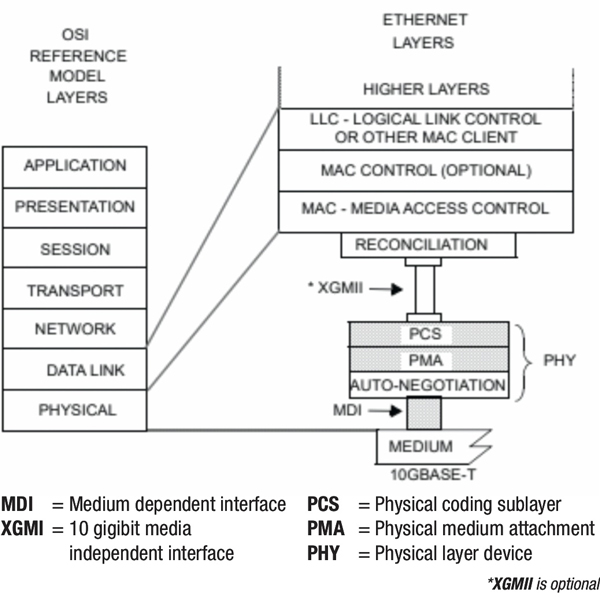
Figure 1. Type 10GBASE-T PHY relationship to the ISO OSI reference model and the IEEE 802.3 Ethernet model.
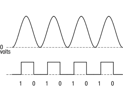
Figure 2. The transition, not high or low voltage, determines bit value.
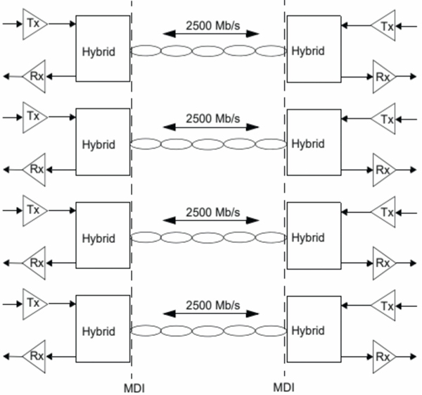
Figure 3. 10GBASE-T topology.
Source for figures: IEEE 802.3 Ethernet standard
 Patrick Hunter — “Hunter”
Director, IT Enterprise Network and Telecom,
Charter Communications
hunter.hunter@charter.com
Hunter has been employed with Charter since 2000 and has held numerous positions, from Installer, System Technician, Technical Operations management, Sales Engineer, and Network Engineer. His responsibilities include providing IP connectivity to all users in Charter’s approximately 4,000 facilities, including executive and regional offices, technical centers, call centers, stores, headends, hubsites, and data centers. Mr. Hunter has served on the SCTE Gateway Chapter Board of Directors since 2005. He spends his spare time mentoring, teaching, and speaking on IP and Ethernet networks as well as careers in the network field.
shutterstock