PNM Upstream Frequency Response? Of Course!
By Bernie Cadieux
With the advent of the latest DOCSIS versions, new technologies emerge and new ideas are founded on the newly available data: full band capture, pre-equalization coefficients, non intrusive measurements, and more. There is no shortage of new software platforms showing us plenty of network impairments that were previously either invisible or very difficult to detect using more conventional testing methods.
Although DOWNSTREAM frequency response has always been a pillar of HFC network health, UPSTREAM frequency response has long been a “more challenging” effort. For the purpose of this article, we will focus our attention to new methods of extracting UPSTREAM frequency response information “in-band” as opposed to the traditional frequency sweeping method that showed HFC network frequency response “out of band” of the signal of interest. The traditional method of frequency “sweeping” the HFC network tends to be costly from a capital investment standpoint and very demanding from the labor force to ensure proper setup so as not to interfere with active signals. It also tends to occupy a lot of rack space, consume power, not to mention that the end result never really provided appropriate network frequency response “in” the band of interest, which is where the actual RF signals exist in the return spectrum. In addition to all this, based on experience and customer comments, many operators actually opt to not activate sweep reference points in between each of the DOCSIS channels, (too risky) which in the end reduces dramatically the resolution of the frequency response in the band of interest. See figure 1 below showing how operators can mistakably set reference pilots too hot and how some avoid inserting reference pilots in between active channels for fear of interference basically blinding any potential interference in the 19.2 MHz of active signal occupation.
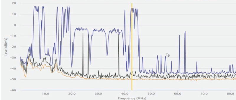
Figure 1: Traditional sweep reference points inserted around DOCSIS channels
The Dilemma
Traditional frequency response sweep systems are not only expensive but they also require very careful setup to ensure no sweep reference points interfere with any active signals in the return, (not the case in the Figure 1 example but the more attentive systems do comply with the vendor recommendations regarding this) being DOCSIS signals, FSK communications, or any other signals currently being used in the US to communicate with various HFC network platforms. The bottom line, it is important to follow vendor specific recommendations to set up pilots at the proper frequency and level so to ensure non-intrusiveness.
The Alternative
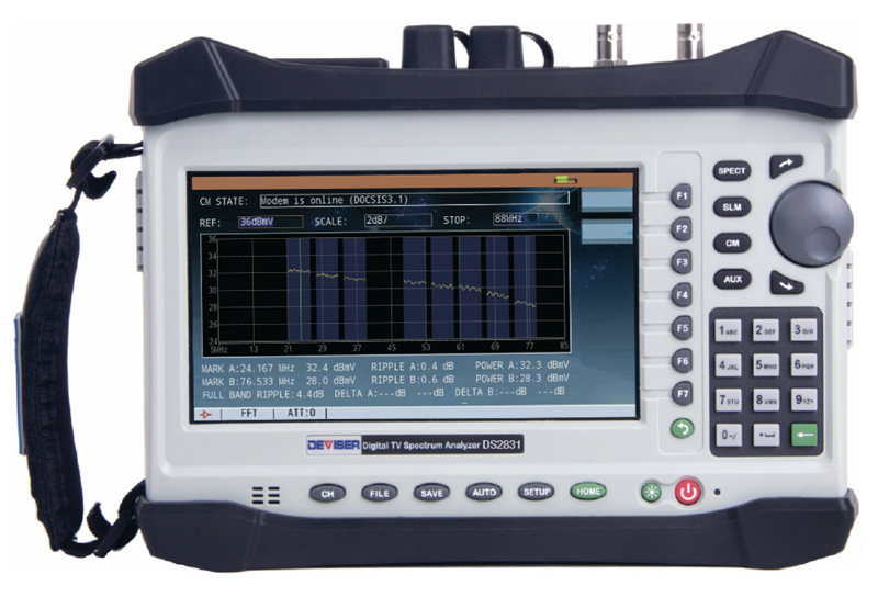
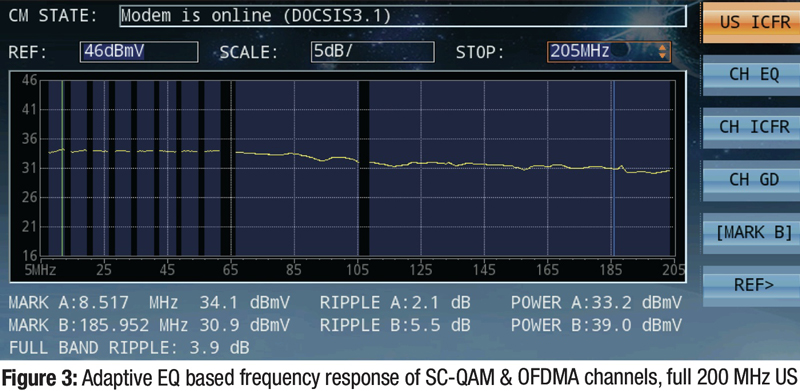
The DS2831 series analyzer, as many of you have already seen and played with, is a new generation true spectrum analyzer that integrates many high performance functions and features. Today we will focus on its ability to represent in-channel/in-band frequency response WITHIN the DOCSIS channels and frequencies of interest. With cable operators now starting to deploy OFDMA channels in the upstream path, and with so many US single carrier QAM DOCSIS signals so desperately needed, it is becoming increasingly difficult to use the traditional frequency response sweep technology. Not to mention upcoming R-PHY or fiber deep technologies and architecture, rendering traditional sweep system harder to use. The DS2831 series analyzer incorporates a fully functional DOCSIS 3.1 cable modem, capable of connecting to your DOCSIS 3.0 or 3.1 CMTS. In a DOCSIS 3.0 environment, the DS2831 series analyzer can provide frequency response information for up to 8x US DOCSIS channels with a maximum of 6.4 MHz each, thus providing in-channel frequency response of up to 51.2 MHz of the return spectrum maximum (see example in the screen pic of Figure 3). In a DOCSIS 3.1 environment, the DS2831 series analyzer can show frequency response information of up to 206 MHz (4 MHz to 210 MHz) with any combination of DOCSIS 3.0 SC-QAM channels (maximum 8x) with a combination of up to 2x OFDMA US channels (maximum 96 MHz each) (see examples of 8x UPSTREAM SC-QAM in Figure 3 above).
The “Real Field” Story
The method used as shown in Figure 3 is actually very simple and avoids scenarios where reference points would be inserted in the wrong location or at the wrong level, being either too low so it cannot be seen by the US sweep receiver or too high and cause the optical link to behave erratically. A single cable modem-to-CMTS connection is established, following DOCSIS protocol in every way, allowing the DS2831 analyzer to then interrogate its internal cable modem’s adaptive pre-equalizer coefficients for each of the SC-QAM channels and/or the US OFDMA channel and convert the captured time information into an “in-band” or “in-channel” frequency response trace, very much like how QAM demodulation equipment in the downstream today shows adaptive EQ information such as ICFR (in channel frequency response) or group delay. This new method of interpreting frequency response will require field operation adaptation but the benefits are many. Adaptation will include longer refresh times when connecting field measurement devices such as the DS2831 series analyzer, somewhat longer refresh times once changes have been made (if required of course) to amplifier pads or EQs. The length of those increased delays will depend on how many SC-QAM and/or OFDMA channels are actually active in the return path. The more active signals, the longer the wait, with possibly 60-90 seconds being the worst case, depending on how good or bad the UPSTREAM HFC network is carrying those active signals.
The Justification
The obvious benefits with this method of extracting frequency response traces are clear:
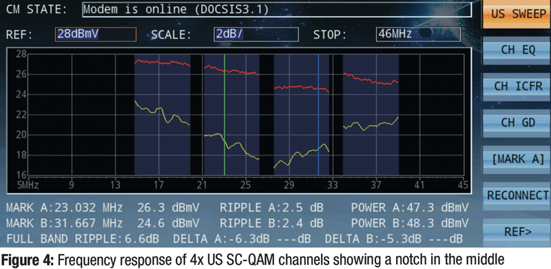
- Better frequency response resolution where it matters most, in-channel/in-band (Figure 4 below clearly shows a notch in the middle of 4x active upstream SC-QAM channels). The red traces in the capture show the stored reference trace at the node, and the yellow traces show live response at the QAM demodulation equipment in the network test point where the notch can be detected. Depending on whether or not traditional sweep systems would have inserted pilot references in the upstream, the cable operator might have been blind to this particular event.
- No UPSTREAM sweep receivers are required (that function being covered by the CMTS)
- No capital expense required to purchase the additional sweep receiver hardware
- Less power consumption in the HE
- Less space being used in the racks
- No risk of interference with sweep reference points traditionally inserted at the field location
- AND, in some cases where the US sweep system was deactivated while not in use, no longer will the field engineers have to call the HE engineers to “turn it on” (basically turning what should be a one man operation into a two man operation again).
 Bernie Cadieux
Sales & Marketing, CATV & Optical group,
Deviser Instruments
bcadieux@deviserinstruments.com
Bernie joined Deviser Instruments in January 2015, with primary responsibilities to the North American market, (Canada, USA, and Mexico) but now expanding to Europe, Australia and Japan. Bernie has 25 years of previous experience with spectrum analyzers and signal level meters at Avantron Technologies and Sunrise Telecom. The latest and upcoming project Bernie is currently working on with his new engineering teammates at Deviser Instruments: upstream frequency response testing with PNM.
408.955.0938