Optical and FTTH Measurement FUNdamentals!
By Steve Harris
As our networks grow with more fiber optic (FO) equipment, cabling, and signaling it is important to understand the types of performance measurements that are used by operators. Knowledge of these measurements will make working with fiber networks “fun,” as well as you performing more effectively in your job role. In this article we explore the common measurements and tools like FO inspection scopes, visual fault locators (VFL), optical power meters (OPM), optical time domain reflectometers (OTDR), and optical spectral analyzers (OSA).
Most operators have a horror story when it comes to dirty FO connectors and FO ports. There have been percentages shared that more than 50% of failures are caused by improper cleaning! The good news is this number is trending downward with the SCTE operational practice training in fiber networks. To combat this issue a FO microscope (“scope”) is used to examine against the International Electrotechnical Commission (IEC) standard #61300-3-35. The IEC standard validates four zones of a FO connector or FO port. As dirt can migrate, the critical, cladding, adhesive (epoxy) and contact (ferrule) zones must be free of contaminants. When any one of the zones does not pass testing, it is important to perform cleaning. Then repeat the inspection to verify correct cleaning and that permanent damage has not occurred. FO scopes are made for a variety of fiber optics including single mode fiber (SMF), multiple mode fiber (MMF) as well as the new multiple-fiber push on (MPO) style connectors.
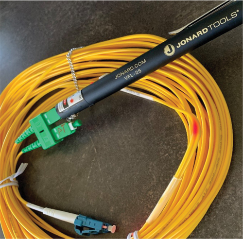
A VFL is another excellent tool to swiftly identify FO breaks, macrobends/stress points, leaks, bad splices or just identify a fiber. A technician may use a VFL pen device (my favorite) to send a 650 nanometers (nm) laser pulse down a fiber jumper to test for anomalies. If the light does not properly exit the end of the FO jumper, there may be a macrobend or break in the jumper. Or perhaps a technician may notice a weakened pulse of light exiting out the middle of the jumper (stress point). When looking for the right portable VFL, choose an option that provides different types of pulses and comes with additional FO adapters for working in high density FO facilities. Finally, check your other optical tools, as they may have a VFL feature.
The next must have FO tool is the OPM or PON power meter (PPM). With a push of a button a technician may quickly identify the FO network’s optical power in units of decibel milliwatt (dBm) or milliwatts (mW). The OPM provides measurements at specific wavelengths (e.g., 1550 nm), while the PPM is designed to test multiple wavelengths (e.g., 1577 nm, 1490 nm). The PPM uses wavelength division multiplexing (WDM) filters to separate and measure individual wavelengths, making it the ideal choice when working within a FTTH network. PPMs are key when determining if the optical power budget of the FO network has been maintained. For example, a technician may measure -29 dBm at the output of an optical tap. If the receive (Rx) optical power sensitivity at a 10G ONU at the premises is -27 dBm, this shows that the optical budget has been exceeded by 2 dB, causing the received power to be 2 dB low. The latest PPM designs support a pass-through port to allow an optical network terminal/unit (ONx) to hear the optical line terminal (OLT). By allowing the ONx to transmit to OLT, measurements can be conducted out-of-band (OOB). Another test often used with OPM, or PPM, is the “attenuation by substitution” test, where a laser is used to generate a signal instead of the FO equipment. This test is often used before activating equipment in our networks.
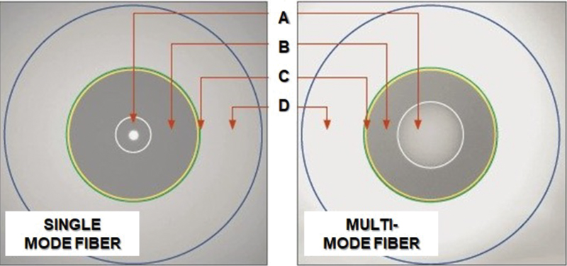
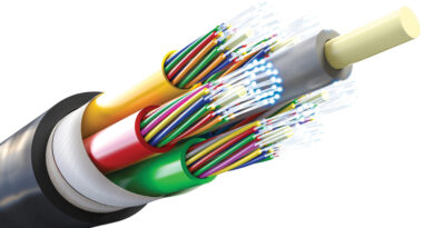
Figure 1. A. Core, B. Cladding, C. Adhesive, D. Contact zones
The OTDR is an another extremely valuable FO tool that provides time (or distance), as well as the physical (PHY) layer transmission characteristics of the glass. The typical PHY characteristics reported by the OTDR’s software are Fresnel reflectance, attenuation (loss), scattering (Rayleigh) and distance measurements. When conducting OTDR measurements a launch cable is used, often called a pulse width suppressor, to get accurate measurements (e.g., bulkhead) and to overcome blind spots in the testing called “deadzones.” The OTDR’s software characterizes the anomalies in the FO network as events, as well as a trace of the fiber. In FTTH troubleshooting, a technician may use an OTDR to launch a set pulse of laser light at a specific wavelength from the premises or optical tap towards the facility to determine if there are defects within a fiber run. Technicians may decrease or increase the pulse width, which is directly correlated to the optical power of the pulse. A larger pulse width will increase the dynamic range of the test while reducing the spatial resolution to detect smaller defective objects and deadzones in the glass. While a smaller width reduces the dynamic range of the test, as well as the dead zones, it also produces a higher spatial resolution examination, as well as distinguishing close events. The results of the OTDR test depend on the optical distribution network (ODN) topology the technician is testing. For example, a centralized split FTTH topology will result in a large attenuation event at the optical splitter, the greatest loss in this type of network. The OTDR is well equipped to report types of splices, connectors and end reflections (or breaks) in the optical cable. In addition, OTDRs are great for final acceptance testing of FO cable reels at the warehouse. For WDM network certification and troubleshooting there are CWDM and DWDM OTDR versions for validating wavelength continuity. Newer small form-factor pluggable (SFP) transceiver modules offer integrated micro OTDRs.
Figure 2. VFL leakage
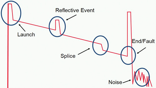
Figure 3. FO launch, trace and events
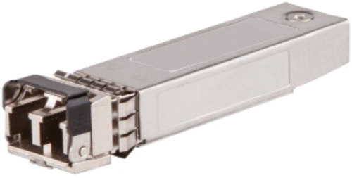
Figure 4. SFP with OTDR
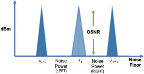
Figure 5. OSNR example
An OSA is not common for technicians, however facility and field engineers use OSAs to perform comprehensive measurements of the tests we discussed previously. OSAs are typically facility racked to perform continuous monitoring of multiple fiber links by an operator’s network assurance team. An OSA performs measurements of wavelengths (channels), optical signal power distribution, WDM and noise power characteristics of light waves. In addition, an OSA can perform the popular optical signal-to-noise ratio (OSNR) measurement.
The OSNR is used for long haul FO networks that contain actives such as amplifiers, which adds noise to the FO link. OSNR is the ratio of the optical signal power to the noise power of the link, or 10*log(S/N). Operators may use an OSNR test to determine why an optical signal within acceptable optical power levels is not being heard at a FO Rx. OSNR tests can also measure Q-factor (qualitative Rx performance) and bit error ratio (BER) values. Q-factor indicates the minimum SNR required for a specified BER. Operators want a good BER that provides a high Q-factor and OSNR.
This article hit on the highlights of the FO tools and measurements. It is our recommendation you keep building your FO knowledge with our online broadband fiber installer (BFI) training and professional certification programs. Having the SCTE fiber optic certification will make you stand out in the crowd and allow you to achieve your career goals much faster than learning on your own!
 Steven Harris
Executive Director, Technical Sales, Learning & Development, SCTE
Steve is an international SME and thought leader, and the executive director of education and business development for SCTE. He is responsible for overseeing the architecture and evolution of educational programs, credentialing, and customized career progressions, as well as business development and partnerships. His team is responsible for an education library that is now 900+ modules, designed to drive business results. With more than 30 years in education, he has taught much of the content of the library, with a dynamic approach to the delivery of highly complex topics.