
New Amplifier Transponders
By Nick Segura and Esteban Sandino
Integration Considerations
Engineering and operations unite!
The time is now for engineering and operations teams to come together for one of the most important opportunities in a long time. With each technology offering comes new operational opportunities, and for cable telecom operatives there is a basal objective to leverage these next-gen technologies in a way to reduce operational costs. Let’s dig into some scenarios for how we could effectively utilize new smart amplifiers equipped with two-way transponders.
As part of an HFC extended spectrum initiative in 2023, operators began collaborating with their amplifier vendor partners and CableLabs® + SCTE working groups towards the adoption of a new communications standard to support the implementation of low-cost, low-power transponder solutions constructed to enable telemetry data collection, and remote management, for modern hardline amplifiers. The engineering community grew optimistic that an industry standard approach could be agreed upon by Q3 of 2024, so it is a great time to consider minimum viable product standards and determine an operational path that makes sense across the board.
Field operations and engineering teams are currently engaged in discussions on how best to integrate smart amplifier telemetry into existing back-office platforms, best methods to collect the most actionable data from the amplifier for logical analyses during remote troubleshooting, effective fault isolation, and optimal dispatching of network technicians to save windshield time.
Transponder considerations for FDD
We begin by looking at transponders from an engineering perspective, and then move to an operations get-the-job-done viewpoint. Transponder minimum requirements assembled from the working group include:
- Standards based—PHY and MAC layer protocols are to follow a standard. Revisions to legacy SCTE 25-1 PHY and SCTE 25-2 MAC standards, plus DOCSIS, and LoRaWAN-based solutions are all under consideration for these new amplifier transponders.
- Reduced cost and power consumption—While the addition of a transponder could yield valuable information and enable some maintenance activity to be conducted remotely, the added costs and power consumption could outweigh the benefits.
- Inclusive of data security—Data encryption will be critical to maintain a secure operating environment. Options under consideration include built-in support for encryption at the MAC layer, or transport and application-layer solutions.
- Support robust PHY layer telemetry carriers with frequency agility in downstream and upstream directions—Single and multiple FSK-based subcarriers are currently under consideration.
- Compatibility with DAA—PHY layer must be compatible with RPDs/RMDs for pass-through transmissions between deployed transponders and associated remote controllers.
- Simplicity—Like anything else, complexity and high equipment failures make this a non-starter.

The time is now—ROI thoughts
Why does it make sense for cable operators to support this smart amplifier telemetry concept now?
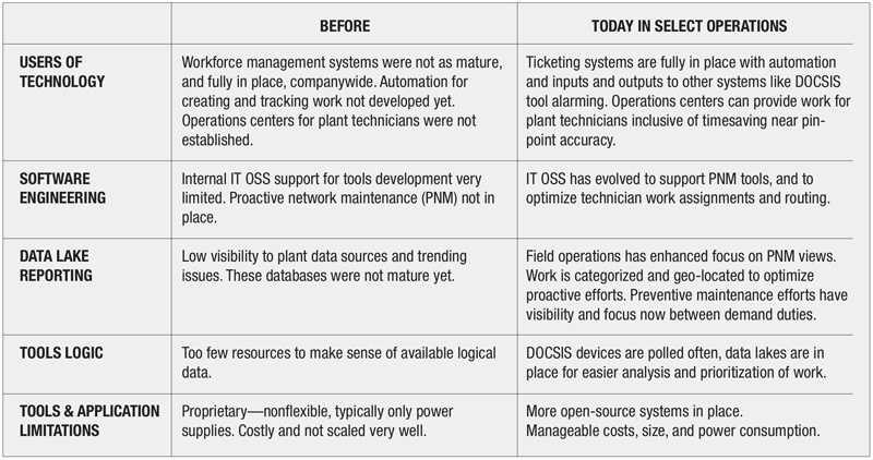
The accompanying table outlines how past efforts to deploy remote monitoring for nodes and amplifiers were generally short lived, and how improvements in today’s operational ecosystems can facilitate more sustainable implementations.
Telemetry use cases—with focus on reliability
Amplifier telemetry data, when coupled with existing software and hardware troubleshooting tools, can turbocharge efforts for correlation and causation, leading to further time efficiencies in day-to-day operations. Some anticipated use cases are outlined in the following sections.
Use case 1—
Upstream ingress detection and localization
- Problem: Upstream ingress
- Impact: Ingress can cause video, voice, and data service issues.
- Current efforts: Upstream monitoring tools are effective; however, remote upstream capture is at the node port so technicians will typically begin there and spend significant time using the divide-and-conquer troubleshooting technique to repair ingress. DOCSIS carrier levels and health are excellent measurements to validate effectiveness of repairs but add limited value to identify the source of trouble.
- Solution: Using transponders in smart amplifiers, along with a network management system (NMS) of sorts, allows for establishing or enhancing a coaxial plant topology. Operations centers can more quickly determine ingress sources by applying a small amount of upstream attenuation to one distribution leg at a time. Efforts around amplifier proximity to impairment, and geolocation, can be provided to technicians to expedite getting to the site where the coaxial shielding is compromised and correct to mitigate the ingress source.
- Upstream wink switches that are remotely controlled can be leveraged to identify which leg, on what active device, has the highest service-impacting ingress source.
- Customer value: Reduced time to repair, or elimination, of service affecting ingress interference. Fewer work zone stops for technicians allowing more preventive work to get done in a day. This also equates to a reduction in fuel and vehicle wear.
Use case 2—
Coaxial cable and connector degradation—identification through AGC adjustment monitoring
- Problem: Plant cable and connector degradation to a point where it is customer impacting—too late.
- Impact: Service quality and reliability performance issues occur for customers. Demand maintenance efforts are required at this point, whereas if operators knew the cable was deteriorating, they could have performed preventive maintenance before signals were impaired.
- Solution: With amplifier diagnostic data we have the potential to see excessive amplifier automatic gain control (AGC) adjustments due to deteriorating plant conditions, which can be detected ahead of signal degradation. Technicians can be readily equipped and mentally prepared to make corrections for active, passive, cable or connector water damage, and compromised RF shielding.
- Operators can leverage the collected data from amplifier AGC corrections over time and set up their NMS to get notified when there is excessive out-of-range activity.
- Vendor amp application may be able to provide calculated linear cable lengths by calculating cable span and passive losses over time. The topology of the amplifiers in the network is available to provide localization of particular problem cable spans, so operators can send a technician to diagnose a specific span of cable between the prior and the problem amplifier.
- If the plant issue is an intermittent or periodic problem, the operator can schedule a truck repair when the problem will be predictably manifested.
- Customer value: Reduced time to repair, or elimination of service affecting ingress interference. Fewer work zone stops for technicians allowing more preventive work to get done in a day. This also equates to a reduction in fuel and vehicle wear.
Use case 3—
Voltage and current monitoring for level variations
- Problem: Missed preventive maintenance opportunities to detect power related issues. The power supply voltage and current feeding amplifiers should not change much unless there is an intentional design or operational change. When the voltage is critically low or if current is unexpectedly high, it could be related to a faulty element in the network. Proactive measures may prevent a service disruption.
- Impact: Reliability of service.
- Solution: With amplifier diagnostic data we have the potential to see an amplifier’s voltage and current, and trend them for changes over time.
- By detecting a value that is outside the set thresholds, operators can determine potential issues.
- Inadvertent plant additions, potentially a faulty bond, physical damage, or water damaged cables and connectors, could be identified and corrected prior to a voltage disruption.
- Operators can determine if, when, and potentially where an additional device or damaged cable creating the additional current draw is located.
- Customer value: Reduced count of truck rolls, faster mean time to repair, improved reliability of service.
Use case 4—
Asset management
- Problem: Inventory tracking and management of amplifiers can sometimes fall short of the desired outcome. Actively monitored amplifiers can augment an operator’s inventory accuracy.
- Impact: Better management of security and network costs.
- Solution: Using smart amplifier manufacturer’s data, we have the potential to track asset information in real-time.
- Tracking amplifier repairs and relocation efforts becomes more accurate.
- Asset management for aging and end-of-life becomes more accurate.
- The ability to track next generation equipment deployments, such as extended spectrum and a new upstream diplexer split configuration.
- Customer value: Up-to-date back-office information, and more efficient field operations.
Use case 5—
Amplifier failure monitor
- Problem: Missed preventive maintenance opportunities to detect failing hardware related issues.
- Impact: Reliability of service.
- Solution: With amplifier diagnostic data we have the potential to see abnormal changes inside of amplifiers, which allows operators to schedule corrective action, ideally prior to services going down.
- Similar to a cable modem, it may be possible to integrate a “dying gasp” message to triage a repeat issue, leading to better warranty and equipment longevity expectations.
- Corrective action can be scheduled during normal maintenance windows to minimize customer impact which leads to higher QoS and lower operating costs.
- Customer value: Supports preventive maintenance efforts, faster mean time to repair, and improves reliability of service.
These use cases are only some of the obvious benefits and tools. Team members will certainly come up with many more.
Conclusion—success criteria
Remote amplifier visibility and control may not seem like a must-have yet. However, with a can-do mindset, operational efficiencies are sure to be gained by leveraging this additional source of intelligence. Whichever transponder technology is deployed, the goodness that can emerge out of this investment can fall under the same title of PNM, because of actionable network health-related diagnostic information.
We have to understand that plant maintenance performed from a swivel chair can be both a blessing and a curse, because there is no substitute for being there in the field ready to act. Just imagine a technician equipped with full visibility to their node areas of responsibility and what they could accomplish ‘if they only knew.’

Nick Segura,
Charter Communications
nick.segura@charter.com
Nick Segura is a Principal Engineer in the Network Technology Group—Outside Plant, and is based in Englewood, Colorado. He is responsible for architecting new technology solutions in the HFC realm to serve the company three to 10 years out.

Esteban Sandino,
Charter Communications
esteban.sandino@charter.com
Esteban Sandino joined Charter in 2018, and holds the position of Distinguished Engineer within the Network Technology Group in Englewood, Colorado. In this role he helps guide the development and implementation of advanced HFC.
Table provided by author, images Shutterstock