IP Networking 101 (Part One)
By Patrick Hunter
After many years of working in field operations in cable, I moved some 10 years or so ago to the network operations and information technology side of the business. As my career took its own twists and turns, my focus went from drop cable, hardline, connectors and the like to Ethernet and IP connectivity, fiber optics, CWDM, DWDM, and more. All along the way, the goal was the same: provide the best possible service to our customers, be they internal or external.
Now, I don’t know if everyone will admit the same, but I have to be honest when I tell you that for many, many years, I really didn’t understand ANYTHING about MAC or IP addresses, what they really meant, or why they even really mattered. What I did know was that MAC addresses were supposed to be unique for each cable modem, and when a customer’s computer managed to get one type of IP address that was a good thing, and if it got another, well, that was bad and that meant that something was wrong. I am now completely willing to admit to you that I was afraid of looking stupid, so I nodded my head and pretended to follow the conversation as I suspect many others did too. This was around the very early 2000s, and I never felt that I had a real need to acquire deep knowledge of how MAC addresses, switching, Ethernet, or IP worked. I was able to do my job as a field technician with minimal understanding of those technologies, but I am convinced that I would have been more valuable to my team and customers had I taken the time to learn how it all worked back then. That’s what I propose to offer you here over the next few installments: a cable perspective from the ground up on what all of that means and how they are interconnected, and most importantly, why any of it really even matters at all.
Let’s start at the beginning. I’ll take you through how information is packaged and sent out toward its final destination and then we’ll look at how the cable plant and equipment play into the transmission. Notice that I leave out wireless, and specialized home routers and other factors in order to simplify the discussion. To tackle the problem of allowing one computer to “talk” to another, the Open Systems Interconnection (OSI) reference model outlines seven “layers” into which most of our information technology transmissions fit today. Take note of the term “reference model,” and realize that even if things don’t always line up identically at the higher layers in what we call the protocol stack, it’s a really good representation of what happens when two computers talk to one another. The idea behind the layers is to allow different network components to process information that needs to be transmitted in their own ways. Each layer serves a specific purpose in the chain of communication. When data (let’s say, for example, the word “Hello”) needs to be transmitted from an application running on one computer to some other computer, the original data (“Hello”) needs to be arranged a certain way and packaged up to be sent on its way. That “package” of information is commonly referred to as a protocol data unit (PDU). It is a very generic term that gets a more specific name based on which particular layer is handling the data. Refer to the diagram below.
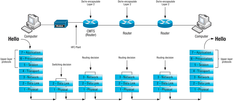
As you can see, the “Hello” is groomed and presented for transmission by the “upper layer” protocols (Layers 5 – 7). Layer 4, known as the transport layer, encapsulates the “Hello” by assigning it source and destination “port numbers,” among other things. This “encapsulation” is the mechanism by which each layer manages the communication process and each of the lower four layers handles encapsulation by its own specific sets of rules (protocols). In the case of the transport layer, this responsibility takes place inside the operating system of the computer (in a sense). So, think of the application handing off the data to the operating system of the computer at this step. The operating system has a portion dedicated to handling all of the transport layer conversations that all of the applications on the computer are attempting to have. Transmission control protocol and user datagram protocol (TCP and UDP) are the typical protocols in use here. You may be familiar with those terms. The port numbers referenced here are how the transport layer keeps track of the different conversations. There is some degree of uniqueness to the way the port numbers are assigned. Once the data has been encapsulated by the transport layer, that piece of information, or PDU, is referred to as a “segment.” You might commonly hear it referred to as a “TCP or UDP segment.” Therefore, the transport layer’s “job,” so to speak, is to keep up with the various conversations with other computers, possibly make sure responses are received, and even throttle the amount of data being transmitted if necessary, depending on network conditions. The transport layer definitely has the capability to be the brains of the operation from the perspective of the lower layer protocols.
Now that the original, well-dressed “Hello” has been passed to the transport layer and encapsulated, and the operating system (transport layer) has taken note of the “conversation” that’s in progress, this newly encapsulated data unit is passed down to Layer 3, or the network layer. The network layer is concerned with IP addressing, which are logical addresses, meaning that you can’t touch or feel an IP address – they just “live inside” a computer. Like its transport layer cousin, the network layer runs inside the operating system of the computer and pays attention to two important things, source and destination IP addresses. The network layer process should know the IP address of the computer on which it runs, whether that address was learned dynamically or if the administrator configured it statically. (Those are the addresses that look a lot like 10.123.21.19). That address would be the source IP address. The destination address may not be immediately known and may need to be learned so the network layer handles the process of finding out what destination IP address should be targeted. Once known, the well-dressed “Hello” that was encapsulated at the transport layer is further encapsulated by the network layer with source and destination IP addresses, among other things. This PDU is referred to as a “packet.” One important distinction to note here is that the network layer does not, like its transport cousin, keep track of the conversation in any great detail. That’s not its job. The network layer’s job is all about routing, or making sure those IP packets get routed whichever direction they are supposed to go. More specifically, this layer makes sure that the packet is routed toward the remote network to which that destination IP address (the other computer in the conversation) belongs. That could be next door or across the globe; the protocol doesn’t necessarily know for certain. A network router may have many different interfaces via which it can route a packet. It just sends the packet the best direction it knows in hopes that it will get where it needs to go.
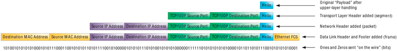
Now that we have the IP packet all ready to be routed to its final destination, the packet is passed down to Layer 2, the data link layer. This layer is focused on physical addressing. Ethernet is the most common Layer 2 protocol in use today. Media access control (MAC) addresses represent the actual physical network interface card (NIC) on a computer. (Those are the addresses that look a lot like 0014:ab25:11e9). You can actually touch and feel the network card, and it is designed to have one unique MAC address assigned to it. That address is the source MAC address in this conversation. When it comes to sending information to a specific computer, it must be addressed to the MAC hardcoded on the NIC for that computer. (I realize that there are exceptions to this rule, but it is a good rule of thumb for the most part.) Based on the destination IP address in the packet that is passed to the NIC, the NIC will be able to decide what the destination MAC address is and further encapsulate the IP packet into a PDU called a “frame.” Since Ethernet is the most common protocol used at Layer 2, the term “Ethernet frame” is equally common. So, since we’ve discussed the “job” of the transport and network layers, what is the job of the data link layer in this case? It is to switch Ethernet frames from one physical location to another. That happens based on the destination MAC address. In the case of our customer’s computer, there is only one place for the frame to be switched: right onto the wire connected to the NIC!
Here is the point at which things can get a little confusing. For the computer on the other end, the destination computer to which our customer’s computer is attempting to connect, our customer’s computer typically never really knows or learns the MAC address of the NIC for that computer. It really only can learn and send traffic to the MAC address of the next routing device headed toward that remote computer destination. Most often, it is the router that is acting as the “default gateway” for our customer’s computer. If the customer’s computer is plugged directly into our cable modem service, then the default gateway is NOT the cable modem, but the cable modem termination system (CMTS) located further upstream in the headend or hubsite. Wait, wait, wait…. How can this be? Isn’t the cable modem the router that connects the customer’s equipment to the Internet? Actually, no. The cable modem is just a Layer 2 bridge, or Ethernet bridge technically. It doesn’t perform any routing or Layer 3 functions with respect to the customer’s computers or Internet service. It simply bridges the customer’s network to our service provider network. “Bridging” is very much the same as “switching.” It’s just switching Layer 2 Ethernet frames from one physical segment to another.
Now we have finally arrived at Layer 1, the physical layer. In the case of our customer’s computer, the physical layer consists of the actual physical components, like the Category 5, 5e, or 6 cable plugged into the NIC. All of the wiring connected between any two NICs is considered the physical layer. When the original “Hello” is all packaged up by the transport, network, and data link layers, all of those ones and zeros (bits) are transmitted onto the physical medium and, if everything works the way we intend, they are received on the other end by another NIC as electrical or optical signals.
In the next installment of our “IP Address,” we are going to dig deeper into the connectivity through the cable modem for our hypothetical customer’s transmission of “Hello.” To this point, we’ve discussed the various layers of the OSI reference model, the encapsulation that takes place at each layer and the responsibility of the various network devices. Next, we’ll walk through the decisions made and how each step along the way can affect transmission. We’ll also cover error detection and correction in the path.
 Patrick Hunter — “Hunter”
Director,
IT Enterprise Network and Telecom,
Charter Communications
hunter.hunter@charter.com
Hunter has been employed with Charter since 2000 and has held numerous positions, from Installer, System Technician, Technical Operations management, Sales Engineer, and Network Engineer. His responsibilities include providing IP connectivity and network security to all users in Charter’s approximately 1,000 facilities, including executive and regional offices, technical centers, call centers, headends, hubsites, and data centers. Mr. Hunter has served on the Gateway Chapter Board of Directors since 2005. He spends his spare time mentoring, teaching, and speaking on IP and Ethernet networks as well as careers in the network field.
Credit: Shutterstock
Credit: Cartoonstock.com