HFC and 5G Backhaul — Two New Friends
By John Chapman
It is amazing how 5G and its disaggregated radio access network (RAN) are similar to DOCSIS/distributed access architecture (DAA)/hybrid fiber/coax (HFC) networks. If you know one, you already have half of the other figured out. For example, both feature a 10 Gbps digital fiber optic cable connected to a radio. For 5G, it is a radio unit (RU) or distributed unit (DU)/RU that feeds an RF spectrum over the air; for DAA it is a remote PHY device (RPD) inside an optical node that feeds an RF spectrum over coax. Both networks are point-to-multipoint and use a scheduled upstream. Both use OFDM/OFDMA. The list goes on.
As a point of trivia, DAA remote PHY (R-PHY) is functionally equivalent to 3GPP RAN split 6 which is also known as the Network Functional Application Platform Interface (nFAPI). Both R-PHY and nFAPI focus on the split between MAC and PHY.
Densification
For both mobile and cable, the higher the frequency, the shorter the distance that the signal travels. For cable, it means shorter HFC amplifier cascades. For mobile, it means more radio locations. Sometimes a lot more. The Small Cell Forum forecasts 38 million small cells will be deployed by 2026 [1]. This is referred to in 5G as densification. All those mobile radios, or small cells, have to be connected to an IP network. That is where the HFC network and small cells can become friends.
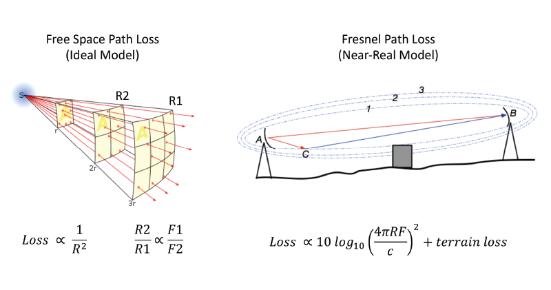
LTE deployment uses the lower portion of the spectrum at about 700 MHz today (as well as up to 2.5 GHz). CBRS will be located at about 3500 MHz. That is a frequency ratio of 5:1. As shown in the free space model in Figure 1, the reach of the small cell is inversely proportional to frequency, so the reach ratio is 0.20. In practice, due to reflectors, scatterers, absorbers, and blockers, coverage is best modelled with ray tracing and reveals a more complex dependency on frequency. This also assumed the Tx antenna, RF path, and Rx sensitivity are the same, which they will not be. In practice, the mobile folks use comprehensive modeling tools for path loss [2]. For our purposes, we will use a reach ratio of 0.09 from [3].
In my 2020 SCTE Expo white paper on small cell traffic engineering [4], I put forth some formulas to calculate small cell densities when compared to macrocells and fiber nodes. If you model an overlapping small cell coverage as a series of squares that fit into a macrocell square/circle area, it could take 125 to 200 small cells to cover 100% of area of one macrocell. That is a lot of small cells. This math and results are summarized in Figure 2.
It should be mentioned that many CBRS operators will not need 100% coverage as they will use LTE as a fallback for low usage areas. Beamforming, a technology marvel but a potentially expensive feature of 5G technology, will increase the effective distance for a given transmit power. So fewer small cells. But the ratio did not account for a lower antenna height, trees, hills, and walls. C-band will go even higher to 4200 MHz. So more small cells. Let’s pick 100 small cells per macrocell for easy math.
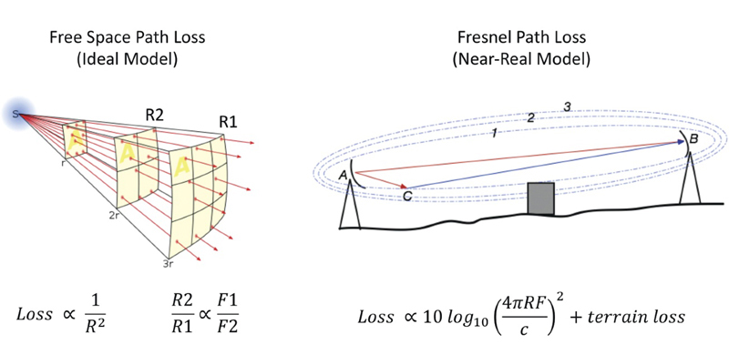
Figure 1. Calculating cell radius when frequency changes
Business economics
Those small cells need a site, power, and backhaul. If a cell tower installation costs $50,000 and there are now 100x the tower sites, that would require $5,000,000. Ouch. With 100x the number of radios, there are not enough towers or money to do the job. Not to mention how long it would take to acquire and deploy those tower sites. Does anyone know of any prevalent broadband technology that passes 93% of the homes passed in the USA, is powered, and has 10 Gbps capability [5]?
That would be the DOCSIS/HFC network of course. HFC has several options for backhaul. The first is dark fiber, so any cell site close to a fiber node location could connect directly to fiber. That will work for fronthaul, midhaul, and backhaul. The second option is coax strand-mount or an attachment to underground coax plant. The third option is an in-home install. Both of these options can work for backhaul and will likely work for midhaul as well.
If all you wanted to do was keep the budget to the billions that were previously spent on LTE, then the new radio sites would have to cost $50,000 / 100 = $500. Is that possible? Well, that is about the price to deploy a cable modem in the home, which is really just a DOCSIS to Wi-Fi radio. So, intuitively, it is possible.
Shaw Communications in Canada did a comparison of connecting small cells via dark fiber versus directly connecting them to the coax of the HFC plant. In downtown Calgary, they were able to deploy strand mount small cells on coax at 1% of the cost and 20x faster-to-deploy than compared with building out a partial fiber infrastructure [4].
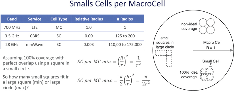
Figure 2. Small cells per macrocell
Implications to the HFC plant
I hope at this point, you are asking yourself how many small cells need to be deployed per fiber node to cover the service area. For a node plus zero amplifier (N+0) HFC plant, it is one to four strand-mount small cells, assuming no trees, hills, or walls. This kind of makes sense. The RPD/fiber node is also a radio. Both the 5G radio and the fiber node have the same task — they transmit similar distances for a given transmit power, antenna gains, and receive sensitivity. Of course, coax is much better at going over hills, past trees, and through walls.
For an N+M plant, more radios are needed. An N+2 plant with 12 amplifiers could require six to 26 stand mount radios. An N+5 plant with 25 amplifiers could require 25 to 100 strand mount radios. This will vary depending on hills, trees, walls, and other obstacles. As a rule of thumb, it appears that the number of radios is roughly the one to four radios times the number of amplifiers. For in-home small cell coverage, it is the number of mobile subscribers per fiber node. An N+5, 500 HHP node, with 20% mobile market penetration, would require 100 indoor small cells. These could be in addition to outdoor strand-mount small cells.
Bandwidth to the rescue
Does this work? Yes. Is there enough bandwidth? Yes. When you replace a single tower with 100 small cells, the primary goal of those small cells becomes connectivity rather than total aggregate bandwidth. In that neighborhood, those small cells will connect to the same things they do today – your phone, your laptop, and your TV. It is the same customer base and the same bits as today. On a well-engineered HFC plant, those bits fit. As a sanity check, CBRS radios are about 100 to 200 Mbps for four channels. This is the data rate of an entry level CM and there can easily be over 100 of those per node. This is a good match.
DOCSIS also has a path to roughly 100x the bandwidth that it has today. The downstream data capacity is in the process of increasing from about 1 Gbps to 10 Gbps. That is the first 10x and is marketed as “10G.” Meanwhile, HFC plant segmentation can migrate from about 500 HHP to 50 HHP. That is the second 10x capacity increase. Together, that is 100x growth potential. This is shown in Figure 3. This is quite impressive and certainly can keep up with the needs of 5G backhaul.
New DOCSIS features for mobile backhaul
There is more good news regarding specific improvements to DOCSIS for small cell backhaul. The first is the DOCSIS Time Protocol (DTP) [6]. DTP allows the DOCSIS network to be used as-is to transfer IEEE-1588 timing from the network to the CM and then to the small cell. This allows small cells in adjacent homes to synchronize their TDD timing. This will become an important feature for CBRS.
The second improvement is for latency. The Low Latency Xhaul (LLX) Protocol pipelines the mobile upstream scheduler and the DOCSIS upstream scheduler [7]. This is done outside of each scheduler, so no proprietary scheduler information needs to be exposed. LLX works by having the small cell send a Layer 3 request message to DOCSIS at the same time it sends a Layer 2 grant message to the cell phone. It gives the DOCSIS CMTS an early view into what is going to happen so that it can accelerate its scheduling and can effectively reduce the DOCSIS upstream latency to a few milliseconds.
Moving forward
We are at the start of the next generation of mobile known as 5G. But the changes are more than just technical, they are also business related. Today’s cable operators are tomorrow’s mobile operators. They, too, will be deploying 5G. Will 5G displace the wireline plant? The reality is that every great wireless network needs a great wireline network behind it. DOCSIS/HFC is a great wireline network and will likely be used to support 5G.
Whether it is wireline or wireless, the real goal is to connect you and your family’s devices to the Internet as fast and as conveniently as possible. Mobile 5G and DOCSIS 10G, the new friends, will likely end up doing that together.
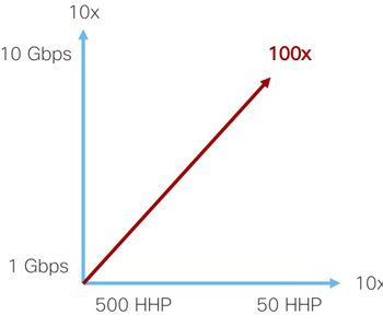
Figure 3. 100x capacity growth potential of DOCSIS
References
[1] SCF market status report July 2020.
[2] F. Perez Fontan and P. Mariño Espiñeira, Modeling the wireless propagation channel: a simulation approach with MATLAB. Wiley, 2008.
[3] “U.S. Telecom and Cable & Satellite Marketing Deck”, MoffettNathanson Research, Apr, 2020, page 120.
[4] John T. Chapman, “Small Cell Traffic Engineering,” SCTE Cable-Tec Expo Fall Technical Forum, Denver, Oct, 2020.
[5] https://www.ncta.com/cables-story, NCTA.
[6] “Synchronization Techniques for DOCSIS Technology Specification,” CM-SP-SYNC, CableLabs.
[7] “Low Latency Mobile Xhaul over DOCSIS Technology,” CM-SP-LLX, CableLabs.
John T. Chapman,
CTO Broadband Technologies,
Cisco
John T. Chapman is CTO of Broadband Technologies and a Fellow at Cisco. John co-founded the cable business unit as in internal start-up at Cisco and has driven innovation in the cable industry since DOCSIS 1.0, including inventing remote PHY, FDX, LLX, DTP, DSG, DOCSIS bonding, DOCSIS CM load balancing, DOCSIS OFDM profiles, and modular CMTS. John is a member of the SCTE Hall of Fame, Circle of Eagles, and the Cable TV Pioneers. He has received three Cisco Pioneer awards, has over 40 publications, and has over 130 filed or issued patents.
Shutterstock