Designing Future HFC Networks — 1.2 GHz and Beyond
By Esteban Sandino
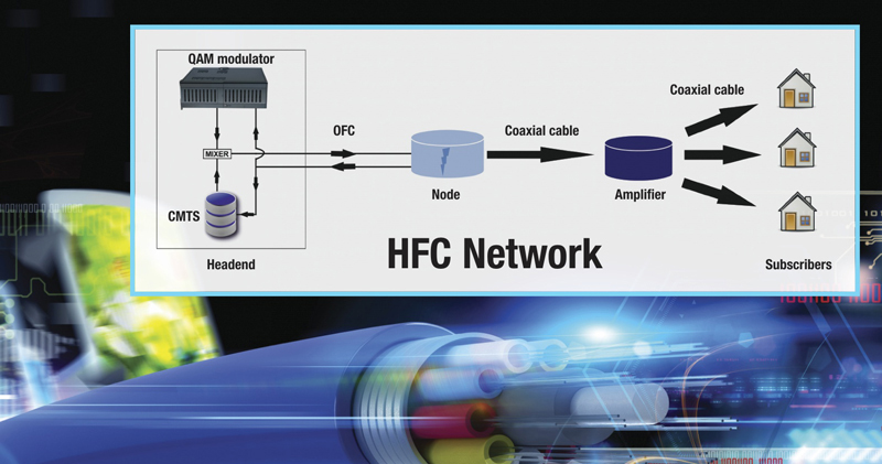
Extended spectrum DOCSIS or ESD represents the next evolution of HFC networks. It opens the door to RF spectrum expansion up to 1.8 GHz, as defined in the DOCSIS 4.0 specification, with the possibility of expanding as far out as 3.0 GHz. Some operators are already considering network upgrades to extend the forward path to 1.2 GHz, and setting the stage for even further expansions. Despite differences in approach amongst operators, future ESD implementations will not mean drastic changes to the tried-and-true HFC topologies. However, that is not to say legacy HFC networks will not require minor improvements such as fiber nodes, RF amplifiers, and network passives to operate at increasingly higher frequencies, and new diplex filters.
Thus, for an operator considering a network upgrade, a thorough understanding of legacy HFC networks and their configuration is required. This will help determine best-fit hardware and design options to optimize costs, while minimizing potential service disruptions. Additional goals may include preserving existing equipment locations, minimizing new cable placements, and upgrading existing hardware over wholesale replacements. These goals, and available equipment upgrade options, must be considered during the planning and design process.
Legacy network discovery
The first step in any design is to gather as much information as possible about the network targeted for an upgrade. Network engineers will face a number of questions. Is it a 550/750/860 MHz or better plant? What is the targeted new upper frequency of operation? What is the condition of the existing hardware? Will new passives be required? If so, is there an opportunity to future-proof the upgraded network and parts? These and related questions demand a methodical approach to the design process. Any operator embarking on this activity will likely follow some basic steps, including:
- Gathering of manufacturer, make and model of RF and optical actives and passives;
- Understanding the mix of hardline cable types;
- Determining plant map accuracy: Are plant extensions properly documented? Are amplifiers spaced per original designs? Will partial or full walkouts be required? Full walkouts are an opportunity to update residential and commercial unit counts, verify cable runs, splice case and power supply locations. However, they add cost and individual operators will weigh that against overall costs, especially if confidence is high in the accuracy of existing maps;
- Determining if plant extensions will be required;
- Listing nodes in need of segmentation to be addressed by the new design;
- Determining the state of the powering network: Are power supplies at or near capacity?
- Understanding current draw and power needs of new nodes and RF actives; and
- Planning for the deployment of any other future devices that draw power from the HFC network, and understanding the impact on the powering design.
A cable operator will likely want to complete the discovery process before determining what active equipment can be upgraded and/or re-used, and the upper frequency limits of existing hardware. This may require bench testing of representative deployed hardware. Depending on age and vintage, some passive gear may support operation beyond their originally specified frequency range while other gear may require upgrades or, in the extreme, full replacement.
RF design process
A primary goal of network upgrades will be to expand usable RF spectrum as much as possible, while maintaining as many existing network components as possible. Available technology options will also dictate what can reasonably be achieved. Regardless of the selected target, currently configured operational RF parameters will impact equipment selection, and selection of new RF tilt and tap levels to accommodate new forward and/or return operating frequencies. Thus, before starting the new design and upgrade of the target network, an operator will want to document the following:
- Forward and return gain and RF levels for fiber nodes, and for distribution actives, e.g., trunk amplifiers, line extenders, etc.;
- Current RF tilt configuration;
- Minimum, maximum and average amplifier cascade lengths;
- Amplifier spacing;
- Gain control configurations, i.e., AGC, manual, thermal;
- Operating frequencies;
- Power supply types and utilization;
- Deployed mix of hardline and drop cable types;
- Designed drop levels;
- Drop-length distributions; and
- Expected equipment in the home: Designing for multiple vs. a single device in the home can impact minimum-drop RF levels significantly, and the cost to achieve those minimum levels.
Once this data is available, a preliminary design targeting the upgrade area can begin. This will require selecting RF parameters such as tilt, and upgraded input and output RF levels for all actives to match or improve legacy end-of-line performance. This process will also update tap levels to accommodate expansion to higher operational frequencies, and determine if tap change-outs or replacements are required. At this stage an operator may want to establish partnerships with equipment vendors to understand technology options and capabilities. Plant powering designs must also be re-visited to ensure power needs for all new actives are met, and to identify any required power upgrades.
Additional considerations
Network engineers will also want to perform an RF noise and distortion analysis. The distortion analysis will likely include, at a minimum, expected system RxMER performance from headend to tap, through the longest amplifier cascade, and using proposed new amplifier RF levels and tilt. Full loading up to the limits of the newly designed bandwidth will also be considered.
Key to the distortion analysis will be whether analog or digital optics will be deployed. Analog optics are limited in their performance and will impact RxMER at the node output. Digital optics feeding an RPD or RMD module in the node will result in higher-fidelity signals and superior RxMER performance. The choice between analog or digital will be up to individual operators after consideration of cost vs. performance tradeoffs.
Lastly, leveraging new RF spectrum without amplifier re-spacing may also require RF booster technologies to raise RF levels at strategic points within the upgraded network. The contribution of these additional actives to end-of-line performance will also impact any distortion analysis.
Design implementation and brief operational considerations
Once a final design has been completed, end-of-line performance verified, and approval received, final design guidelines for HFC design teams will usually follow. An operator may also choose to arrange vendor training for new replacement equipment to familiarize designers with updated RF upgrade levels and other design parameters.
Field teams will also want to understand upgraded operational RF levels. Operators may want to address items such as meters to cover expanded frequency ranges, ensuring technicians are equipped with the right pads and equalizers to support upgraded areas, and training to understand configuration differences between legacy and upgraded areas. Finally, customer care challenges arising out of potential interference in the home between legacy CPE and modems operating in an expanded RF spectrum will most likely need attention.
The steps and design process outlined here are not new to experienced cable operators but are merely a reminder of some of the key challenges any operator might face when preparing for RF spectrum expansions. The current environment is simply another opportunity for the cable industry to do what it does best. That is, rise to the challenge of building and expanding on HFC as one of the most successful, cost-effective and ubiquitous networks around. The HFC network can continue to deliver for many more years in a cost effective manner when the right steps are taken.

Esteban Sandino,
Charter Communications, Inc.
esteban.sandino@charter.com
Esteban Sandino joined Charter in 2018, and holds the position of Distinguished Engineer within the Infrastructure Architecture & Engineering team in Englewood, Colorado. In this role he helps guide the development and implementation of advanced HFC architectures and technologies. Esteban has held leadership roles in technology development and technical operations throughout his career, and holds multiple patents. Esteban holds a Bachelor of Engineering degree in Engineering Physics. He is a member of both the IEEE and SCTE, and also a member of the SCTE Rocky Mountain Chapter.
Image: Shutterstock


