Getting a CIN Ready to Support FMA/R-MACPHY Deployment
By Deependra Malla
To meet the growing demand of bandwidth and to support the next generation of multi-services, in 2018 Cox decided to transform its analog access network infrastructure to digital fiber network by implementing a converged interconnect network (CIN) and a distributed access architecture (DAA). As Cox continues to evolve its legacy access network to a DAA and a CIN based network to support remote PHY and DOCSIS 3.1, it’s already time to think forward to support an FMA/R-MACPHY deployment support from the CIN perspective. Since the FMA/R-MACPHY architecture introduces SDN capabilities in the access network by separating the control plane and data plane, it will have significant impact on how we design, build, and operate the new CIN.
DAA Architecture: R-PHY vs R-MACPHY
In a DAA architecture, several functions of an integrated CCAP are moved from headend to the nodes in the field. Based on what functionalities are moved to the node, there are two variants of a DAA architecture — remote PHY (R-PHY) and remote MACPHY (R-MACPHY) architecture. In the R-PHY architecture, only the DOCSIS PHY functionality is relocated to a remote PHY device (RPD) whereas in the R-MACPHY architecture, both the DOCSIS MAC and the DOCSIS PHY are relocated to a remote MACPHY device (RMD). Figure 1 shows the conceptual topology of a R-PHY and a R-MACPHY architecture as it pertains to the Cox network.
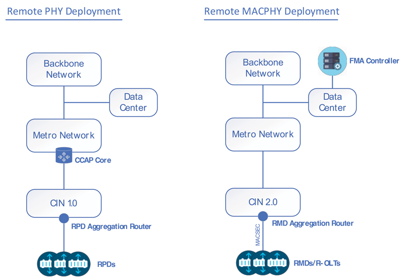
Figure 1. Cox conventional vs future CIN topology
Cox Conventional CIN Architecture (CIN1.0)
As shown in Figure 1, the remote PHY architecture requires a CIN to connect CCAP cores to RPDs. Cox’s conventional CIN infrastructure (CIN 1.0) is built on native IPv6 only and leverages loop-free communication using routing protocols like IS-IS and BGP and uses zero touch provisioning (ZTP) to deploy a large number of RPD aggregation routers. It is a true IPv6 fabric that provides a non-blocking, highly elastic, extensible network, and supports flexible any-to-any connectivity between RPDs and CCAP cores. This flexibility allowed RPDs at a remote headend with space and power constraints to connect to a CCAP at a different headend. In Cox terminology, this is called an “Extended-CIN (E-CIN).” For the E-CIN to provide a successful and stable connection between RPDs and CCAPs that are not collocated at the headend, it is essential to have a symmetrical routing using the shortest optical path between host CCAPs and remote RPD aggregation routers. Since CIN1.0 lacks advanced traffic engineering capabilities, to maintain a symmetrical routing and keep the latency sensitive traffic on the optically shortest path between host CCAPs and remote RPD aggregation routers, we perform manual traffic engineering based on IGP cost.
Cox Future CIN Architecture (CIN 2.0)
As CableLabs defines and solidifies the specifications and interoperability of the remote MACPHY architecture in the form of flexible MAC architecture (FMA), it is time for Cox to think about the new CIN architecture that supports RMDs and R-OLTs. R-MACPHY delivers all benefits of R-PHY in addition to reduction in headend devices, reduction in network latency and improved quality of services. Another benefit Cox gets by deploying RMDs is that it doesn’t need E-CIN thus eliminating manual IGP based traffic engineering.
Although R-MACPHY is a natural evolution of R-PHY, it will not replace R-PHY immediately in Cox’s network. So, both technologies will co-exist in Cox’s network for the foreseeable future. Various factors like network architecture, scalability, integration existing infrastructure etc., need to be considered while designing a new CIN 2.0 network. With 25G capable RMDs on the horizon, there will be increased bandwidth demand in the new CIN 2.0 network. Hence, the new CIN 2.0 network will be built on evolving higher speed interfaces like 25G and 400G.
Remote MACPHY technology decouples the control plane from the data plane and brings SDN/NFV features into the access technology. All DOCSIS based management can now reside on a centralized FMA controller. Elimination of a centralized CCAP requires moving Layer 3 functionality (IPv4 and IPv6) of the CCAP to a metro router in the CIN 2.0 network. In Cox’s network, we can design the CIN 2.0 in two ways:
- Hub-and-spoke architecture with Layer 3 termination on spoke routers (Figure 2)
- Clos-based spine-and-leaf architecture with Layer 3 termination on spine routers (Figure 3)
Both architectures are highly scalable and widely used in the Cox network. Each network can terminate a large number of hosts to its edge devices and can easily scale east to west. In a hub-and-spoke architecture, we can utilize existing metro aggregation routers as hub routers and insert feature rich 1 RU devices as spoke routers to aggregate RMDs. The spoke router hosts a gateway for v4 and v6 addresses for customer traffic. This means the spoke routers needs all Layer 3 features that are currently supported by CCAP routers and should scale to large numbers of MAC, ARP, ND and DHCP relay caches. The spoke router will run all protocols (BGP, ISIS, SR) and is responsible to provide connectivity to the Internet for customers. This architecture is simple to maintain and troubleshoot, elastically scalable and provides a disaggregated solution with reduced blast radius in case of issues on spoke routers.
In a Clos-based leaf-and-spine architecture, a leaf can be a regular 1 RU switch capable of supporting a large number of MAC addresses only. The Layer 3 gateway for customers’ v4 and v6 traffic resides on spine routers. So, these spine routers will be feature rich Layer 3 routers which can support massive scale of MAC, ARP, ND and DHCP relay caches. Within a Clos architecture we can run EVPN-VXLAN to overlay Layer 2 features over a Layer 3 network. This architecture provides a centralized solution from a Layer 3 perspective, however it is complex to maintain and troubleshoot and has an increased blast radius.
Regardless of the architecture, the new CIN 2.0 RMD aggregation devices (spoke or leaf) must be able to support MACSEC. MACSEC will be utilized to encrypt Layer 2 frames between an RMD and an edge aggregation router to preserve data integrity in the Ethernet link.
In the new CIN 2.0, Cox will utilize segment routing (SR) to label switch traffic from gateway routers to respective regional aggregation routers. The SR deployment will simplify protocols, provide 50 ms failover using topology independent loop free alternate (TI-LFA) and support tactical traffic engineering using SR-TE if needed. It also opens the possibility of network slicing using flexible algorithm where we can have multiple planes or slices of the network based on various network attributes such as link delay (delay optimized slice) or link bandwidth (bandwidth optimized slice).
As Cox embarks towards the journey of FMA/R-MACPHY architecture, the experience gained from running the CIN1.0 network will prove vital in designing, implementing, and operationalizing the new CIN 2.0 network. The new CIN 2.0 network will have tremendous impact on Cox’s digital access network evolution and its modernization.
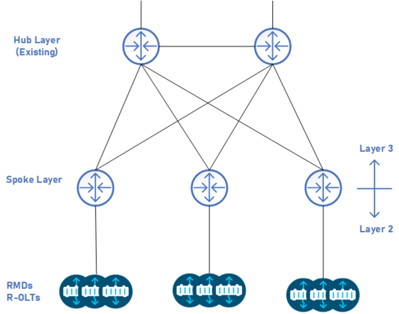
Figure 2. CIN2.0 — Hub and spoke topology
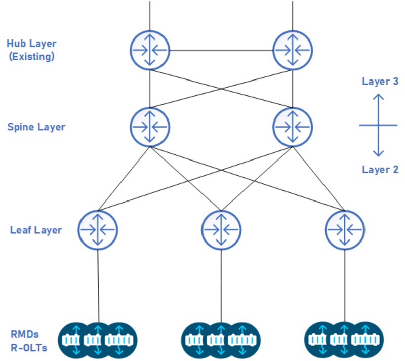
Figure 3. Spine and leaf topology
 Deependra Malla,
Lead Network Design Engineer,
Cox Communications
deependra.malla@cox.com
Bill Warga,
Deependra Malla is a Lead Network Design Engineer at Cox Communications. In his current role at Cox, he is responsible for researching, designing, and implementing new technologies in Cox core backbone and metro networks. He tested and deployed CIN in Cox metro network. He holds MS in EE from Wichita State and MBA from Washington State University and is a CCIE in R&S (CCIE #42229).
Figures provide by authors