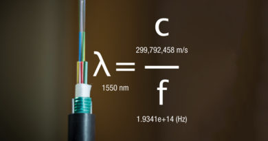
A Guide to Optical Splits to Improve your Fiber Game!
By Steve Harris
In many of our access and core architecture networks, operators are increasing their utilization of fiber optic technologies. This is because optics are passive and very effective at transporting large quantities of data over great distances. Optics also play well with other popular transport mediums like coax and Wi-Fi. Optical signaling and data are distributed across an operator’s core network, as well as over an access network to arrive at a customer or business premises. These optical signals are transmitted (Tx) and received (Rx) at deliberate power levels expressed and measured in milliwatts (mW), an absolute optical power level. Absolute levels may also be represented as a relative optical power level, known decibel milliwatt or dBm.
The reason operators use a defined power level is to meet the criteria of an engineered optical power budget. The budget is the operational specification used to design, maintain, and troubleshoot an optical network. These budgets are used in HFC, fiber deep, FTTH and distributed architectures. For FTTH, the specified optical distribution network (ODN) budget allows the optical signals to meet the receive sensitivity of customer premises equipment (CPE) in the field, as well as the return to the optical line terminal (OLT). When this budget is exceeded, the network will not perform correctly and must be re-optimized.
With other advances in optical networks, a single fiber optic cable, or point-to-point (P2P) connection, from Tx to Rx is not often used to send signaling and data to customers. There are more preferred options that utilize higher fiber counts, optical multiplexing, and optical signal division. For example, in a FTTH downstream signal, an OLT acts as the Tx and the optical network terminal / unit (ONx) acts as the Rx. In the upstream the ONx is the Tx, and the OLT is the Rx. An OLT may talk to 32 or more ONxs over a single fiber optic cable that is part of a high fiber count (ct.) cable. This type of design is referred to as point-to-multipoint (P2MP).
As mentioned, a single fiber connection often does not exist as operators use high fiber ct. cables to create the connectivity required in the network. High fiber ct. cables may be 72, 288, 576, or even as high as dense ribbon at 3456 ct. Many options exist in the marketplace. In addition to high fiber cts., each fiber may be multiplexed and/or split. Multiplexing allows operators to use multiple wavelengths over a signal fiber. For example, an operator may want to send 1G EPON/GPON 1490 nm and 10 EPON/XGS-PON 1577 nm wavelengths downstream. Multiplexing at the optical level is often referred to as wavelength division multiplexing (WDM), coarse WDM (CWDM) and dense WDM (DWDM).
To further optimize the performance and utilization of an optical network, optical signal splitting is employed. An optical splitter may have one or more inputs and multiple coupled outputs to reach a set of Rx. These splitters play an important role in optical networks like FTTH. Understanding their operation will improve one’s ability to design, maintain, and troubleshoot these ODNs.
Let us start with why operators split optical signals. These reason may vary by operator, as it may be to preserve fiber density in areas of the network that are starved for space or reduce density in other cases. Another reason may be to optimize existing aerial or underground fiber investments without having to re-construct or overbuild. Finally, operators may also want to keep some existing fiber ct. for future projects, creating dark fiber.
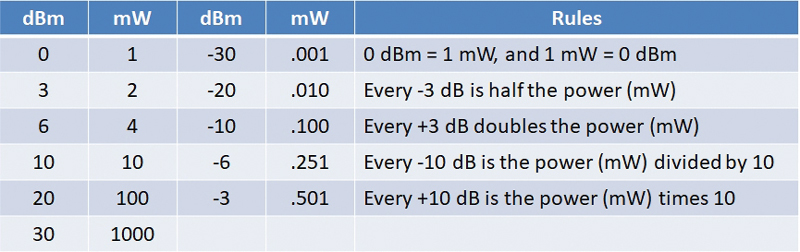
Figure 1. mW to dB optical power levels.
What is an optical splitter then? An optical splitter is a passive device, meaning is does not require power to operate like an optical DWDM amplifier in a fiber deep HFC. The purpose of an optical splitter is to separate incident light beams from a downstream OLT into several light beams for downstream to ONT/ONUs. In the upstream these beams are combined. A basic optical splitter would be a one by two (1:2) configuration that separates a single beam into two light beams. An important takeaway here is to understand each time the optical signal is split the optical power is reduced by half, meaning 2 mW is now 1 mW or 0 dBm, plus excess loss. See Figure 1. Another example would be a one by four (1:4) splitter that receives 6 dBm on the input and reduces the power to 1 mW, Figure 3.
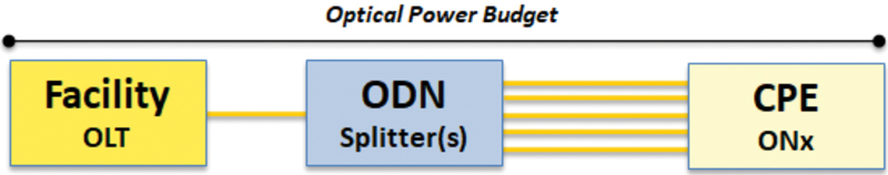
Figure 2. FTTH optical network budget.
A key message here about optical splitters is the power reduction must be known to account for in the engineered power budget. In addition, the reduction of power from splitters and other components must still meet the requirements of the ONx’s Rx sensitivity. Typically, optical splitters contribute the greatest loss in a FTTH network as operators use higher versions like 1:32, 1:64 or even 1:128. The greater the split the more ideal loss is created, not accounting for port or excess loss. Take for example a 1:32 splitter where light beam is reduced by five times or a total of 15 dB (3 dB x 5) of ideal loss.
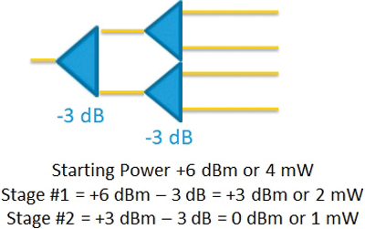
Figure 3. One by four optical split example.
For a typical FTTH deployment, the most popular approach for optical signal distribution is the centralized single split, resembling a tree topology or P2MP, shown in Figure 4. Centralized split is the easiest to troubleshoot as the topology is the least complex. Alternative topology designs are available, referred to as the distributed split and distributed tap/segmented split. These designs are similar. Distributed split uses multiple splitters between the OLT and the ONx, providing a greater ability for customization. The distributed tap lays out the fiber taps similar to an HFC design, placing optical taps in similar positions where coaxial taps may have appeared in the network. A final design applied in more rural builds is called fiber indexing. Shown in Figure 4, an operator will drop fiber #1 to a local premises’ terminal feeding splitter #1, while additional fibers continue deeper in the access network to connect other premises. The additional fibers are moved up as they exit the terminal or indexed, where fiber #2 exits as fiber #1 to feed the next terminal. This will continue in a daisy chain fashion to feed over 200 homes.
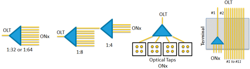
Figure 4. Central, distributed, distributed tap and index optical split designs.
The next time you go to work in the optical network, take notice of the optical power budget, as well as the type of optical split designs used in the network. Also, note that designs may vary from system to system, as operators may use different tactics to provide connectivity to their customers. Recognizing these items allows a technician to swiftly optimize and troubleshoot a fiber network. Be prepared to work with dB, dBm and mW to measure and maintain correct optical power levels in the network. Get familiar with optical multiplexing as well. There are a few previous articles that will support you in these areas. Finally, earning the SCTE broadband fiber installer (BFI) industry-recognized credential for FTTH is a must. This credential will allow a technician to stand out from their peers and stay up to date on fiber optic network technologies!
 Steven Harris
Executive Director, Technical Sales, Learning & Development, SCTE
Steve is an international SME and thought leader, and the executive director of education and business development for SCTE. He is responsible for overseeing the architecture and evolution of educational programs, credentialing, and customized career progressions, as well as business development and partnerships. His team is responsible for an education library that is now 900+ modules, designed to drive business results. With more than 30 years in education, he has taught much of the content of the library, with a dynamic approach to the delivery of highly complex topics.