Using Passive Radar in Cable Operations
By Tom Williams
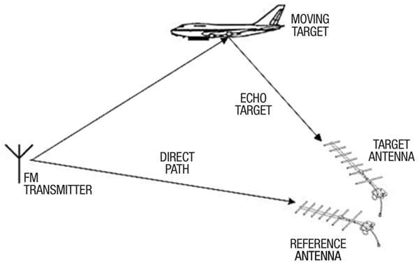
Active radar is a well known method to locate objects in the air and is based on sending a probing signal out and receiving reflections to determine distances and bearings to objects such as ships, aircraft, or UFOs. In military applications there is an undesirable side effect of a radar transmitter revealing itself to an enemy. There is an alternative, which is passive radar. With passive radar the transmitter is an already-existing signal, such as a UHF digital TV broadcast. At a different receive site, two directional antennas are used, one pointed at the broadcast tower, and the other pointed at a target. See Figure 1 which is a diagram of passive radar. The two received signals are processed together to find the target and the clean broadcast signal is used as a required reference signal to locate objects.
This same idea is extended to cable lines, but implementation is way easier. Reflections from a cable line indicate damage, such as animal chews, craft error, mechanical damage, bullet holes, or corrosion. Previously the cable lines needed to be taken out of service to make a radar-type measurement with an instrument known as a TDR (time domain reflectometer). Taking cables out of service for routine and preventive maintenance is no longer an option because cable is now providing lifeline services. At the fiber node’s outputs, the coaxial lines can be probed for reflections to indicate damage locations, and severity of damage. This passive probing can be done without interruption to two-way services. Broadband downstream signals transporting random data are captured and analyzed with DSP to find reflections. Basically, if a delayed copy (a reflection) of the transmitted signal is observed, the time delay is noted, and the reflection’s amplitude is recorded. Time delay is linearly proportional to round-trip distance, just like aerial radar, and can be readily computed using a factor known as velocity of propagation. This factor is simply the fraction of the speed of light at which signals propagate in the cable.
It is possible using a pair of probes (called directional couplers) to get two separate signals from the plant, the clean downstream reference and upstream reflections from the plant. But an even simpler solution exists, just sample the two already-combined signals with a single probe. The two signals are easily distinguishable because one is a time delayed copy of the other.
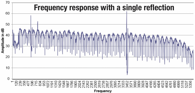
The field test equipment can be cost reduced even more if a low-cost spectrum analyzer is employed. With a reflection, the combined signal’s spectrum will have a characteristic called a standing wave, illustrated in Figure 2, where the combined signal’s amplitude varies with frequency. The reciprocal of the frequency difference between two peaks reveals the distance to the reflection. If there are multiple reflections, the envelope of the signal can be processed with an inverse Fourier transform to reveal individual reflections.
A couple of operational caveats should be pointed out. The first is that a clean reference is required, just like on aerial radar. If the clean reference is already contaminated with an echo, confusion on the analysis reigns. A second is that the processed signal display should look to a technician as much as possible as the output of a conventional TDR, the instrument with which he/she is familiar.
In conclusion, passive radar also works on cable lines, and a block of already-present digital carriers makes an excellent test signal.
SCTE·ISBE Network Operations Subcommittee Working Group 7, chaired by Comcast’s Larry Wolcott, is studying methods like that discussed in this article to simulate TDR functionality.
 Tom Williams,
Distinguished Technologist,
CableLabs
Tom Williams is a Distinguished Technologist with CableLabs. He received his BSEE from Christian Brothers University, his MSEE from the University of Illinois, and his MBA from Eastern Illinois University. He has worked in the cable industry for 40 years, first at Scientific Atlanta (now Cisco), then at CableLabs, and then as a contractor/consultant, and is currently back with CableLabs. While at CableLabs, Tom has tested digital broadcast signals for compatibility with cable plant, and evaluated the ability of cable lines to transport high-speed digital signals. Currently, Tom is working on PHY-layer issues associated with delivery of gigabit data over cable networks, and advanced network diagnostics. Tom is a prolific inventor with more than 60 patents granted or pending, and enjoys radio frequency (RF) design and digital signal processing (DSP).
Charts provided by author