MPLS — What is it? In Plain English, Please…
By Patrick Hunter
Once upon a time, there was routing…and there was switching. For me, keeping it that simple was important because if you muddied those waters, I was really lost. Even though I knew from lots of water cooler conversation that there was so much more to networking in the world, I just refused to allow any of that other clutter to get into my head to that point.
Once I felt I had a pretty good handle on what routing and switching are and how they worked normally, I began to ask around about this mysterious thing that kept coming up in conversation. I heard many different people discussing “MPLS” and it seemed to pop up a lot, but never in any discrete way. It was always this vague thing that people mentioned, quite casually, as if everyone should know about this mysterious multi-protocol label switching (MPLS) and what it does. So, I began asking around among my peers. And an interesting thing kept happening. I really wasn’t able to get a straight answer out of almost anyone. Some engineers would tell me some vague notions about “label switched paths” but not really anything concrete that I could relate to my existing basic knowledge of routing and switching. It seemed so odd to me that a topic it appeared everyone knew so much about could be so impossible to explain. Turns out, it wasn’t that hard to explain, it’s just that being able to put complex ideas into simple language is much harder than it seems. The brightest among us do struggle with this task quite often.
So, I had to learn as best I could on my own through research and digging into the many devices in my network that might be part of the magical MPLS universe. And it was actually quite an enlightening exercise, to be honest. Now, to steal a phrase from my colleague, grab a very strong cup of coffee and let’s dig in.
It is important to note that this builds on our previous discussions around routing (“A Closer Look at Routing,” Broadband Library Fall 2018) and switching (“Ethernet in a nutshell,” Broadband Library Spring 2018). Remember that each switch in a local area network (LAN) has the function of switching Ethernet frames quickly and efficiently within the local network, and each router has the responsibility of making sure to route packets headed for remote networks (or between different LANs, however you’d like to look at it). There are inherent inefficiencies for a router to perform its routing table lookup via software, especially at very high speeds, and there are limitations to what the switching model can do for us in that they are specifically designed to operate efficiently within their local network, not so much across a larger wide area network (WAN).
But, if we could find a way to leverage the genius of routing intelligence and the hardware-driven performance characteristics of switching, we just might have something magical. And that’s indeed what happened when MPLS was created. Now, to be fair, the use of application specific integrated circuits (ASICs) for doing fast packet-switching arrived in time to refute the notion of speed as a true benefit of MPLS. But one can’t deny that faster packet switching in any form is a good thing for network performance. Additionally, what MPLS brought to the network world, especially for service providers, is a transport technology that could allow many different types of networks to be unified, like IP, asynchronous transfer mode (ATM), frame relay or others. As technology changed and ATM and frame relay networks have been replaced by all-IP networks, the benefits of MPLS continue to abound. The biggest advantage today is MPLS’s ability to provide seamless virtual private networks (VPNs) for both Layer 2 (like Ethernet) or Layer 3 (IP, silly) traffic.
In all fairness, MPLS isn’t really just an amalgamation of Ethernet switching and IP routing. In fact, the idea of how to packet switch information really goes back to frame relay and ATM networks. The ability to label packets of information to help determine which direction to send them without really looking at IP addresses was captured very well by the older data link layer technologies. MPLS really just works along the same lines. Let’s get into that now.
In MPLS terms, the “label” part of the abbreviation is very important. Essentially, as a participant in an MPLS network, a router can be informed of a destination prefix, or subnet, and what label to assign to that particular prefix. What that means is, when an MPLS router receives a labeled packet, it doesn’t need to perform an IP routing lookup to determine the best direction to send the packet, but rather just look at the label already wedged into the packet and determine what to do with the label and where to send the packet. Picture it like this: It’s as if the entire path from one end of the network to a particular destination is already picked out ahead of time, usually based on routing protocol information, so that the packet can be more efficiently switched to the destination.
There are a number of ways that a router can learn about what labels relate to which prefixes. For each individual router, the labels are only locally significant, meaning not all of the other routers in the MPLS domain really know about the specific label (it’s just a number). But when all the routers on the way to a destination have the label-prefix association in their label information base (LIB), they together form a label switch path (LSP) that represents the entire path from some source to destination prefix.
Now, the source in question is just specific to the entry point of a packet into the MPLS domain. Figure 1 shows a simplified version of an MPLS domain. There are routers that exist within the MPLS network or domain, and they communicate with each other via a specific label distribution protocol to set up the LSPs. There are other routers that are outside of the MPLS domain that simply forward IP traffic like a normal router.
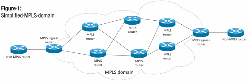
Figure 2 shows us a bit of the process in the actual creation or setup of the LSP. For this part of the discussion, the action happens from right-to-left in the diagram. The router at the edge of the MPLS domain knows about a particular network, say 10.8.0.0/24 by virtue of its routing table. Aside from the fact that its MPLS neighbor routers probably already know about this particular network, our MPLS egress router notifies them that to send an MPLS labeled packet toward that network, the packet should arrive with the label “25”. That label will notify the router that the packet needs to have the label removed and routed to the appropriate direction. The router that received that label advertisement now does the same thing and notifies its other neighbors about the path, but sends them a different label — one that is significant only to itself. The process repeats until label advertisements have been sent to all of the MPLS-aware routers. The green line in Figure 2 actually shows us the LSP from end to end through the MPLS domain after the label advertisements have completed.
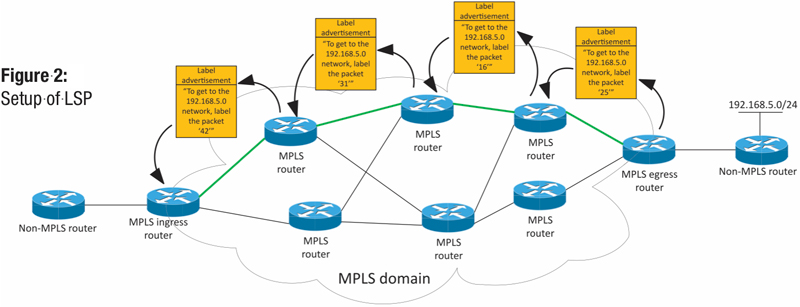
Interestingly, the routers in the middle of the cloud, the MPLS routers that are not on the edge of the MPLS domain, don’t ever really even know about the destination prefix at all when traffic is actually forwarded across the MPLS domain. They just know that if they see a packet labeled with a label that is in their LIB, they need to replace the label with one that means something to the next router (in its LIB) and send it on the way. Effectively, instead of routing the IP packet as a router normally would, it is label switching the packet. No routing table lookup needed, no need to examine the contents of the packet, including the source or destination IP addresses.
Figure 3 shows us how the processing of an IP packet would work in the scenario set up by Figure 2. This scenario is the more natural left-to-right flow to which we are accustomed. An IP packet is generated somewhere outside our MPLS domain, and it arrives as our MPLS ingress router. That router has an “aha!” moment and realizes that an LSP exists in its LIB and it must label the packet in order that it can be label switched through the MPLS domain as opposed to being routed normally. Each successive router has its own “aha!” moments along the way. (To be perfectly honest, they don’t really say “aha!” to themselves. That feature is only available in the 19.2.5.3.992 Hyperion code train, and it’s super expensive but only adds flashiness. I don’t recommend upgrading to that particular version.)
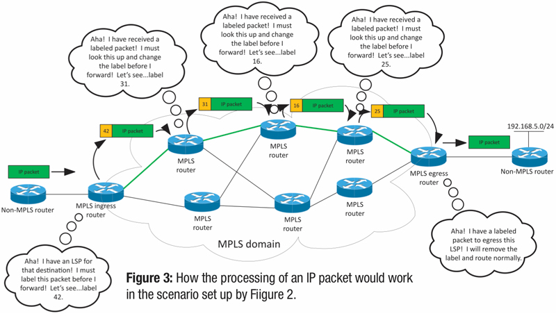
For each MPLS router, the label is examined, a lookup is done, and the packet continues to be label switched until it arrives at the MPLS egress router. At this point, the label actually gets dropped altogether and the packet again is routed normally. Now, the magic of label switching is not entirely obvious looking at this example, but there is something special that the functionality affords us.
Because the contents of the packets don’t get examined, and the LSP is really essentially hidden from the rest of the routing that takes place in the network, the LSP itself is virtually a private network in a sense. So, by virtue of creating an MPLS path through the network, we’ve created our own VPN (see the sidebar “What is a VPN?”). The LSP functions like a VPN tunnel. For the path from the ingress router to the egress router, there isn’t a way for other networks or devices to somehow intercept the labeled traffic. It really qualifies as a form of VPN. But, it gets even better. There are two very popular types of MPLS VPNs used today, and in fact both represent the vast majority of MPLS use throughout the service provider universe.
What is a VPN?
Virtual private networks (VPNs) are methods (software and/or hardware based, depending on implementation) that encapsulate packets in such a way that they can traverse a public network securely, and that the “encapsulation” allows, say, a remote connection to perform as if it were a dedicated, direct (and private) connection to a private network.
Layer 3 MPLS VPN
The first use case is the Layer 3 MPLS VPN. As you have noticed in reading these articles in “IP Address,” the third layer of the Open Systems Interconnection (OSI) is the network layer, which for us usually means IP addresses and IP routing. In Figure 4, we see an example of this type of MPLS VPN. We’ve described the routing table for routers many times, and that table is generally known as the “global” routing table in a particular routing domain. But, if you notice in the network in Figure 4, you can see that there are private routing tables that are associated with the Layer 3 MPLS VPN for this particular scenario.
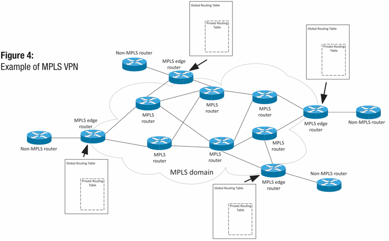
Generally, those private routing tables are fed from the non-MPLS routers and remain in sync with each other. It’s as if there are little mini-routers inside of the MPLS routers that host a privately routed network for a customer. Pretty slick, huh? I liken it to the service provider MPLS network acting as one giant router or routing instance from the customer’s perspective. It’s important to note that in the Layer 3 MPLS VPN use case, the non-MPLS routers — or “customer edge” routers — peer with the MPLS routers or “provider edge” routers, as they are commonly called. That is a regular routing protocol peering from the customer’s point of view. Most often, border gateway protocol (BGP) is the preferred protocol in this arrangement.
One of the great operational benefits of this technology is that the MPLS routers (the non-edge routers) don’t even have to know about the existence of the VPN or the private routing tables at all. Just because they only label switch packets when they receive them, they don’t ever need to know anything about those silly little details!
Another great point to bear in mind is that, because the routing tables for this VPN scenario are truly private, the customer (who really owns the routing table here) can use IP addressing that overlaps the service provider or other customers and never have to worry about an IP conflict due to this overlap. It’s totally private!! But wait, there’s more…
Layer 2 MPLS VPN
The second use case is the Layer 2 MPLS VPN. It is an interesting use of the MPLS-driven VPN solution. It is most accurately referred to as any transport over MPLS, or AToM. The idea is that MPLS can transport not just Ethernet frames, but any Layer 2 solution, again such as frame relay or ATM. The variations on this technology can be emulating a single Ethernet cable, by creation of an Ethernet over MPLS (EoMPLS) pseudowire (that’s a fancy term). This is commonly known as an Ethernet line (E-LINE) solution. Essentially the MPLS VPN mechanism makes the service provider network feel just like plugging into an Ethernet cable. From the perspective of the customer, the MAC addresses learned (remember, this is Ethernet) from this connection are those MAC addresses of the customer devices on the other side of the EoMPLS pseudowire. In effect, the MPLS network is transparent.
Another variation on the AToM solution is an Ethernet LAN (E-LAN) emulation service. This solution basically uses the same underlying architecture as the E-LINE solution, but instead aggregates multiple EoMPLS pseudowires to a common bridging location somewhere in the service provider network. In effect, this makes the entire service provider network look and feel like an Ethernet switch to the customer.
Figure 5 shows us the breakdown of encapsulation and labeling in an MPLS environment based on the scenarios just described. The first frame is a simple Ethernet frame with an IP packet for its payload, just like we discussed in the fall 2017 issue of Broadband Library (Networking 101). The second shows how labeling works for simple IP over an MPLS network. The label is shimmed or wedged in between the Ethernet header and the IP header. This is the simplest use case for MPLS.
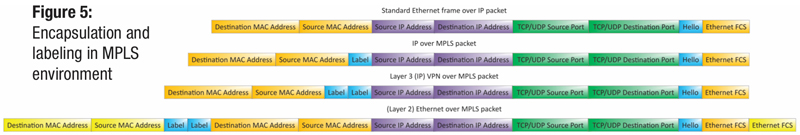
The third frame shows us what happens in the Layer 3 MPLS VPN example we discussed. Two labels are used, one to identify the LSP across the domain, and one to identify the specific VPN domain. The fourth frame indicates the Layer 2 MPLS VPN (AToM) frame structure. The entire Ethernet frame from the customer router is encapsulated inside two MPLS labels (just like Layer 3 MPLS VPN) and the locally-significant Ethernet frame is built around that payload. This is the means by which the MPLS domain seems transparent to the customer, and appears that they are directly plugged into their own device.
As you can see, there are many applications of MPLS, and it has proven to be a powerful, scalable solution. Most, if not all, service providers have MPLS implementations available in their service catalog. For flexibility and data agnostic transport, it’s still pretty hard to beat MPLS as a solution.
 Patrick Hunter — “Hunter”
Director, IT Enterprise Network and Telecom,
Charter Communications
hunter.hunter@charter.com
Hunter has been employed with Charter since 2000 and has held numerous positions, from Installer, System Technician, Technical Operations management, Sales Engineer, and Network Engineer. His responsibilities include providing IP connectivity to all users in Charter’s approximately 4,000 facilities, including executive and regional offices, technical centers, call centers, stores, headends, hubsites, and data centers. Mr. Hunter has served on the SCTE Gateway Chapter Board of Directors since 2005. He spends his spare time mentoring, teaching, and speaking on IP and Ethernet networks as well as careers in the network field.