Grasping the Theory of Fiber Optics
By Steven Harris
Many of the folks that attended SCTE·ISBE Cable-Tec Expo 2017 in Denver were able to realize the growing evolution of our access networks. The transport medium of choice for these future cable access networks and next generation services will be fiber optic cabling. As I shared in my previous articles, operators are focused on improving the quality of the network and transforming them with new fiber deep, FTTx, and distributed access architecture (DAA) technologies. These modern designs will require more of our cable workforce to characterize fiber, making it important to understand the theory, operation, and troubleshooting of fiber optics.
A single fiber is created from silica glass, a pure form of glass that allows for total internal refraction or TIR. The fiber has three distinct physical components: a core, cladding, and coating. The signal used is in the form of electromagnetic energy primarily traveling down the core or optical waveguide. The core has a higher index of refraction (IoR) than its corresponding cladding which confines the signal and prevents it from escaping the waveguide while at the same time providing TIR. The coating is designed to protect both the core and cladding. The core size of a fiber will vary depending on which mode is used by operators. Two popular modes used in our industry are single mode fiber (SMF) with a core size of 9 microns (micrometer or μm) and multimode mode fiber (MMF) with a typical core size of 50 or 62.5 μm. SMF has only one mode of light traveling down a core while MMF has a larger core diameter allowing multiple light modes. Many operators are using multiplexing such as coarse or dense wavelength division multiplexing (CWDM/DWDM) to send multiple signals (different wavelengths or colors of light) over the same SMF because it supports a greater distance than MMF.
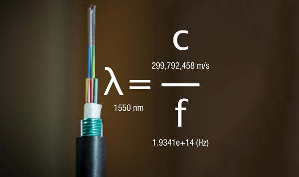
The frequency (f) and wavelength (λ) or lambda are inversely related, where the wavelength (λ) equals the velocity of the wave (v) or speed of light (c) divided by its frequency (f) in hertz (Hz). The higher the frequency, the shorter the wavelength. For example, technicians must recognize that a 1310 nanometer (nm) wavelength has a higher frequency in terahertz (THz) than a 1550 nm wavelength. FTTx networks are designed to use a variety of wavelengths (e.g., 1490 nm and 1610 nm) over different optical bands to achieve connectivity.
Other important aspects of fiber are the design characteristics of mode field diameter (MFD) and spectral bandwidth. MFD is a critical performance specification that technicians must adhere to during splicing and connectorization of fiber, because the MFD value of fiber and connectors must match for optimal performance in the network. Larger MFD values are more sensitive to macrobending, so be certain to handle the fiber with care! The small range of wavelengths emitted by a transmitting laser is referred to as the spectral bandwidth, where various wavelengths travel at different speeds. A portion of the spectral bandwidth is peak power, which is represented by a decibel unit referenced to 1 milliwatt (mW) or dBm. The dBm is used to characterize optical power in the network.
Related to design characteristics, fiber has intrinsic and extrinsic factors associated with its performance. Intrinsic factors are determined during the manufacturing of a fiber and a technician typically does not influence them. Intrinsic factors include glass impurities, material absorption, scattering, dispersion (smearing) and reflection of a signal. The extrinsic factors are crucial, because a technician may influence them with improper handling or installation. Common extrinsic factors include bend loss and alignment. Bend loss, also referred to as macrobends, occurs when the fiber is physically bent, causing electromagnetic power to leave the core of the fiber into the cladding. Bending loss is greater at longer wavelengths and may be unavoidable, newer bend insensitive fiber (ITU-T G.657) is being used by operators today. The other extrinsic factor, alignment, occurs during splicing, mating, or connectorization. It is critical to take the time to avoid alignment issues in the network. In addition, there are many points of attenuation such as connectors, mechanical splices, fusion splices, and macrobends. Overall it is important to understand the desired engineering loss budget, which is the sum of component and fiber losses in a fiber link.
Finally, a fiber network needs to be characterized to maintain its operation. There are a variety of tools that fiber technicians work with, including optical power meters, optical time domain reflectometers (OTDR) and fiber scopes. Want to learn more? We encourage you to explore the training opportunities (SCTE.org/FTTx) and all the fiber related webinars (SCTE.org/LiveLearning) located within SCTE·ISBE.
 Steven Harris
Senior Director, Advanced Network Technology and Instruction, Learning and Development, SCTE•ISBE
Steve Harris is the senior director of advanced network technology and instruction at SCTE•ISBE. He is a respected international telecommunications subject matter expert, sought-after presenter and principal instructor. He is responsible for the tremendous growth of SCTE•ISBE training programs and certifications for over 100,000 telecommunications professionals. He also has responsibility for the client partnership in the SCTE•ISBE Corporate Alliance Program for cable operators and vendors.
Source: Shutterstock