Understanding DOCSIS 3.1 Cable Modem Transmit Power
By Brady Volpe
A cable modem’s transmit power is extremely important. It not only determines if the cable modem will be able to come online and register with the CMTS (cable modem termination system) but obtaining the optimal transmit power will make or break the subscriber’s quality of experience (QoE). A DOCSIS 3.1 cable modem’s transmit power introduces some new considerations which are discussed in this article.
Why is DOCSIS 3.1 cable modem transmit power important?
Transmit power per channel is defined as the average RF (radio frequency) power in the occupied bandwidth (channel width).[1] Transmit power per channel of a DOCSIS 3.1 cable modem is important for several reasons. First, every modem has a minimum and maximum transmit power. Having too little or too much attenuation between the modem and CMTS will exceed the minimum or maximum transmit power of the cable modem, which will cause the modem to fail to communicate with the CMTS. Frequently, failure to have enough transmit power to communicate with the CMTS is a key reason that modems are unable to register with the CMTS or the root cause for modems to frequently drop offline and re-register (often called flapping modems).
Next, to achieve the optimal signal quality or receive modulation error ratio (RxMER), the HFC network should be configured to force the cable modem to transmit its signal above the noise floor while leaving headroom to transmit more power when needed. This ideal spot has typically been between 40-50 dBmV. The lower limit of 40 dBmV elevates the modem’s signal out of the noise floor in the HFC plant. The upper limit of 50 dBmV assumes four-channel bonding. The maximum transmit power per channel of 50 dBmV allows for 1 dB of additional headroom. If more than four channels are bonded in the upstream, a cable modem’s max transmit may be limited to 48 dBmV if it does not include the extended transmit ECN [MULPIv3.0-N-10.0943-5]. Recommendations on nodes with more than four channel bonding should be lowered on the high end to a maximum transmit power of 47 dBmV.

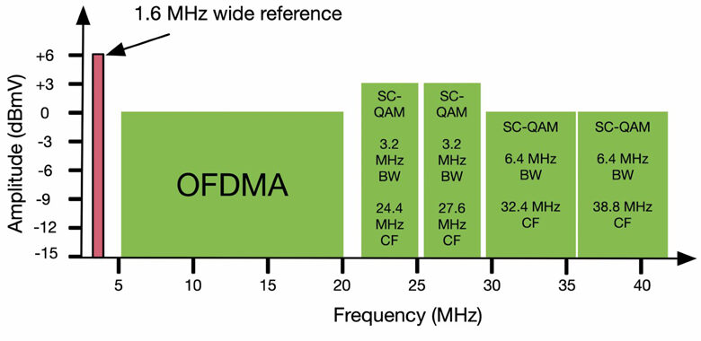
Figure 1. Upstream bonding group (UBG) with one OFDMA and four SC-QAM channels (1.6 MHz wide channel shown in red for reference purposes only
Finally, DOCSIS 3.1 and 3.0 cable modems have a limit on the dynamic range that the modem can have its lowest transmitting channel to its highest transmitting channel. This is called the dynamic range window (DRW) and is limited to 12 dB. While this seems like a large window, return paths have tilt as well as other impairments which can quickly exceed the 12 dB window. In particular, the DRW can easily be exceeded due to degraded in-home wiring. This will result in the cable modem being unable to use all upstream channels, a condition known as partial mode. For a deep dive on DRW, please review this YouTube video John Downey and the author created specifically on understanding DRW: https://youtu.be/CJAKmQ2u7pk
How is DOCSIS 3.1 cable modem transmit power set?
A cable modem’s transmit power is always controlled by the CMTS. Typically, CMTSs are configured for a constant input power per carrier of 0 dBmV. However, this is vendor specific and can also be changed by the user. As an example, the CMTS used in this article was configured by the author for an input receive power level of 6 dBmV for SC-QAM (single carrier quadrature amplitude modulation) channels and 0 dBmV for OFDMA (orthogonal frequency division multiple access) channels.
Power calculations in a DOCSIS 3.1 CMTS are based on constant power per carrier in the upstream with respect to a 1.6 MHz bandwidth channel. While CMTS vendors may have proprietary methods to set upstream channel power, the DOCSIS 3.1 specification has defined channel power to be measured within a 1.6 MHz bandwidth or P1.6r_n. The “n” in the P1.6r_n, value indicates the number of equivalent DOCSIS channels in the occupied bandwidth as divisible by 1.6 MHz. For DOCSIS 3.1, the equivalent channel power for legacy SC-QAM channels is also calculated based on chunks of 1.6 MHz spectrum, again defined as P1.6r_n.[2]
What does all of this mean to upstream receive power at the CMTS? The CMTS upstream channels have been configured as shown in Figure 1 with one OFDMA channel and four SC-QAM channels. Also, added in Figure 1 for visual purposes is a red 1.6 MHz reference channel just below 5 MHz.
The red 1.6 MHz reference channel shown in Figure 1 has a reference power level of +6 dBmV. A DOCSIS 3.1 CMTS that measures power with respect to a 1.6 MHz channel (P1.6r_n) and is configured to have its SC-QAM input level at 6 dBmV would adjust a cable modem’s transmit power so that the receive level at the CMTS of the 1.6 MHz channel is set to exactly +6 dBmV. The cable modem is transmitting 3.2 MHz and 6.4 MHz SC-QAM channels. The CMTS will adjust their power based on the 1.6 MHz reference. One can easily calculate the actual level the CMTS will set the 3.2 MHz and 6.4 MHz channels using the following formulas:
Delta = 10log10(1.6 MHz / 3.2 MHz) = -3.01 dB
This means the 3.2 MHz channels will be 3.01 dB lower than the 1.6 MHz reference channel or +2.99 dBmV. Similarly, we can do the same for the 6.4 MHz wide SC-QAM channel:
Delta = 10log10(1.6 MHz / 6.4 MHz) = -6.02 dB
This means the 6.4 MHz channels will be 6.02 dB lower than the 1.6 MHz reference channel and 3.01 dB lower than the 3.2 MHz SC-QAM channel.
OFDMA channel power is also measured with a 1.6 MHz bandwidth reference, like the SC-QAM channel. No calculation is required for OFDMA because OFDMA channel power is always configured with respect to the 1.6 MHz reference.
Even though the peak levels in Figure 1 may look different, the total input power for each channel is measured with respect to a 1.6 MHz bandwidth reference. Further, the per-channel power for all of the SC-QAM channels is identical, even though the heights of the “haystacks” are different.[3]
Estimating a DOCSIS 3.1 CableModem Transmit Power
Now that the expected receive power at the CMTS is known, how can one estimate the transmit power of the cable modem?
The cable modem is only aware of its absolute transmit power and is not aware of the receive level at the CMTS. The CMTS sends relative power level adjustments to the cable modem to obtain the desired receive level at the CMTS.
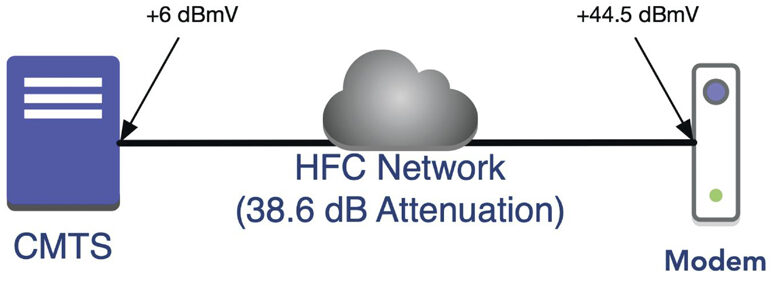
The resultant transmit power of the cable modem represents the loss between the output connector of the cable modem to the input connector of the CMTS. One can think of the HFC network as an attenuator, which the cable modem must overcome. This is illustrated in Figure 2.

Figure 2. Simplified network diagram, HFC network as an attenuator
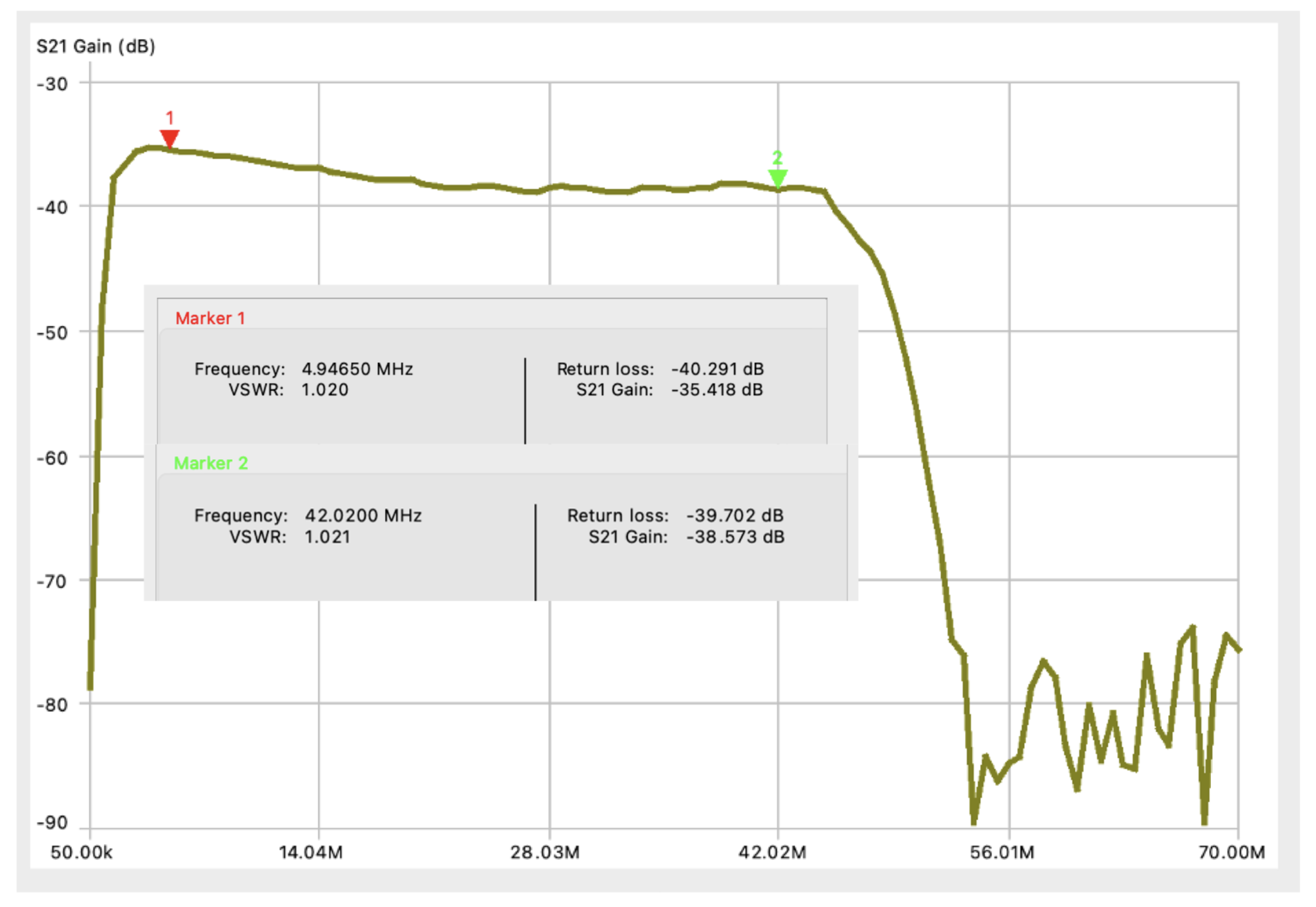
In a lab network, it is possible to measure the attenuation from the cable modem to the CMTS. Measurement of attenuation is called insertion loss. Figure 3 shows the insertion loss measured in the lab network used in this article.
Figure 3. Insertion loss of lab network from cable modem to CMTS. Marker 1 at 5 MHz, Marker 2 at 42 MHz
In the frequency response of Figure 3, a marker at 5 MHz shows an attenuation (insertion loss) of 35.4 dB at 5 MHz and 38.6 dB at 42 MHz. These values will be used to estimate the transmit power of the cable modem.
The CMTS expects to see a receive power of +6 dBmV for SC-QAM channels. There is 38.6 dB of attenuation (insertion loss) between the CMTS and the cable modem for the four SC-QAM channels. Based on this, we can estimate that the modem should have a transmit power for the four SC-QAM channels of:
Estimated SC-QAM Tx Power = +6 dBmV + 38.6 dB = 44.6 dBmV
This indicates that the four SC-QAM channels should be transmitting at 44.6 dBmV to reach the CMTS with in input power of +6 dBmV.
Similarly, the OFDMA channel can be estimated as follows, using the 1.6 MHz bandwidth reference for transmit power:
Estimated OFDMA Tx Power = 0 dBmV + 35.4 dB = 35.4 dBmV
Based on the estimated plant loss and known CMTS input power, one can conclude that the DOCSIS 3.1 cable modem should be transmitting SC-QAM channels around 44.6 dBmV and the OFDMA channel around 35.4 dBmV. Looking at the CMTS command line, it is possible to see the exact transmit power of the DOCSIS 3.1 cable modem shown in Figure 4.

Figure 4. Actual modem transmit power as reported by CMTS
Figure 4 shows the first channel is the OFDMA channel which is transmitting at 36.00 dBmV. The estimated transmit power was 35.4 dBmV, an error of 0.6 dB. The SC-QAM channels are transmitting at 44.25 dBmV for the first SC-QAM channel and 44.50 dBmV for the remaining three SC-QAM channels. The estimated transmit power was 44.6 dBmV for a maximum error of 0.35 dB.
Conclusion
Although it possible to estimate a DOCSIS 3.1 cable modems transmit power, it would be quite difficult to do so in a live HFC network. It is more important to focus on ensuring cable modems are transmitting in an optimal range, typically between 40-47 dBmV, assuming four or more DOCSIS channels. Understanding the DRW will become increasingly important as the upstream is increased to 85 MHz or 204 MHz. Finally, understanding power measurements, such as 1.6 MHz reference, total power, channel power and power spectral density are becoming increasingly more important as their definitions are integrated into the DOCSIS 3.1 specification.[4]
References
[1] CM-SP-PHYv3.1-I16-190121, Physical Layer Specification, Section 7.4.12.2.
[2] IBID
[3] More on Total Power and PSD, see Ron Hranac’s article here: https://bit.ly/bbl_psd
[4] IBID
 Brady S. Volpe
brady.volpe@volpefirm.com
Brady Volpe is Founder of The Volpe Firm, Inc and Nimble This LLC. He has over 25 years of broadband cable and telecommunications industry experience specializing in RF, DOCSIS, PNM, and Internet Protocol. Mr. Volpe has been providing a wide range of troubleshooting, design solutions, services and seminars for cable operators and broadband companies specializing in DOCSIS, System Design, PNM, and Troubleshooting. He is a highly respected published speaker, both domestically and internationally. He also hosts a popular industry YouTube and Podcast – “Get Your Tech On“. Mr. Volpe has a MSEE with honors and a BSEE.
Shutterstock


